Advertisement
RGB LED Illuminophony
kits
The key to a successful event is not only a good
music, but also good lighting. Presented RGB LED
controller circuit will even meet the expectations of
the fussiest of partygoers.
Circuit description
Electrical diagram of the device is shown in Figure 1. It
consists of a microcontroller, an operational amplifier
and power transistors. The input signal is provided by
the C1 capacitor to the input of the operational
amplifier. The input polarising voltage is determined
by a divider made up of resistors R9, R10, R13, R14.
The microcontroller (ATmega8) is clocked by an
internal RC generator operating at 8 MHz. Analogue
signal from the audio amplifier is measured using an
A/D converter and is delivered to the
PC0 input. The program 'selects' components in the
following frequency ranges from the audio signal:
High: 13...14 kHz.
Medium 6...7 kHz.
Low 500 Hz...2 kHz.
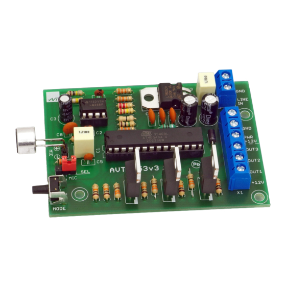
Specifications
• working with LED strips or RGB modules
• single channel load: 3A
• selectable input signal:
- microphone (MIC)
- LINE IN socket
• 7 effects to choose from
• power supply: 12 VDC
• board size: 79×58 mm
The programme then calculates the light intensity
value for each channel and controls the output
transistor in proportion to the result. Activators are
transistors T1...T3 (BUZ11) with a high current-
carrying capacity. There is a LINE IN input on the
board for direct input of an AUDIO signal of 0.7 V
(typical headphone output). You can select the sound
source using the SEL jumper: CINCH (RCA) or
microphone (MIC).
PDF
DOWNLOAD
ASSEMBLY DIFFICULTY
1
Advertisement
Table of Contents

Related Manuals for AVT 1853

Summary of Contents for AVT 1853
- Page 1 RGB LED Illuminophony kits DOWNLOAD ASSEMBLY DIFFICULTY The key to a successful event is not only a good Specifications music, but also good lighting. Presented RGB LED • working with LED strips or RGB modules controller circuit will even meet the expectations of •...
- Page 2 2.2K US2A 390K US2B LINE LM358N 330R LM358N 220K 100K +12V +12V 7805 +12V +12V OUT1 MEGA8-P OUT2 PC6(/RESET) PC0(ADC0) OUT3 PC1(ADC1) PC2(ADC2) AREF PC3(ADC3) AVCC PC4(ADC4/SDA) PC5(ADC5/SCL) 330R PB6(XTAL1/TOSC1) 330R PB7(XTAL2/TOSC2) PD0(RXD) PD1(TXD) 330R PD2(INT0) PD3(INT1) PD4(XCK/T0) PD5(T1) PD6(AIN0) PD7(AIN1) PB1(OC1A) PB0(ICP)
- Page 3 Operation You select he effect using the MODE button (S1): - Red. - Blue. - Green. - White. - Illuminophony. - Changing colour randomly to the bass rhythm. - Off. List of elements Resistors: R1-R3, R17:....330 Ω (orange-orange-brown-gold) Marker R4-R7, R18: ....10 kΩ...
- Page 4 AVT SPV reserves the right to make changes without prior notice.Installation and connection of the appliance not in accordance with the instructions, unauthorised modification of components and any structural alterations may cause damage to the appliance and endanger persons using it. In such a case, the manufacturer and its authorised representatives shall not be liable for any damage arising directly or indirectly from the use or malfunction of the product.
Need help?
Do you have a question about the 1853 and is the answer not in the manual?
Questions and answers