Advertisement
Quick Links
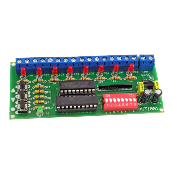
8-Channel LED Controller
kits
The controller is equipped with eight outputs to
directly control of light emitting diodes or relays,
through which they can then switch on any high-
power equipment. The light sequences are not
imposed - each user programs them independently. It
is possible to program a sequence consisting of 124
steps maximum. This programme is stored in non-
volatile EEPROM memory of the microcontroller. It is
possible to play a recorded sequence once or to play
it in a loop. Playback speed can be adjusted by
pressing two buttons in 27 steps from 0.05 second up
to 30 seconds/step.
Circuit description
Electrical diagram of the controller is shown in
Figure 1. Operation of the circuit is controlled by a
microcontroller ATtiny2313 timed by an internal
clock signal . The controller must be supplied with
a voltage of 12 V DC connected to the VCC
connector. The D1 diode protects the circuit from
incorrect polarity of the input voltage. The U1
stabiliser provides the +5 V voltage, while the C1-
C4 components filter it. As an output amplifier for
the individual controller channels, the ULN2803A
chip was used, which contains 8 transistor amplifier
stages with protection diodes for direct control of
relays. The circuit outputs can be loaded with up to
Specifications
• eight outputs to control light sources
• number of programme steps: 124
• very simple programming of lighting effects
• control of various types of output systems,
e.g., LEDs or relays
• UP/DOWN keys to adjust the speed of change
playback
• operating status indication: LED
• load capacity: 200 mA / channel
• supply: 12 VDC
200 mA / channel. To program the sequence the
SW1 switch of the DIP SWITCH type was used. LED
indicates recording sequence in programming
mode and in operation mode it indicates system
activity by blinking. Three buttons S1-S3 are used
to operate the module. In normal operation, the S1
button is used to replay the entire sequence, S2 to
reduce the playback speed and S3 to increase it. In
programming mode, S1 is used to save the step,
while S2 and S3 are used to complete the sequence
creation procedure and select how to play it back.
PDF
DOWNLOAD
ASSEMBLY DIFFICULTY
1
Advertisement

Related Manuals for AVT 1881

Summary of Contents for AVT 1881
- Page 1 8-Channel LED Controller kits DOWNLOAD ASSEMBLY DIFFICULTY The controller is equipped with eight outputs to Specifications directly control of light emitting diodes or relays, • eight outputs to control light sources through which they can then switch on any high- •...
- Page 2 4,7k 4,7k 4,7k ULN2803 RESET (SCK)PB7 OUT1 (MISO)PB6 OUT2 (MOSI)PB5 OUT3 OUT4 (OCI)PB3 OUT5 OUT6 (AIN1)PB1 OUT7 (AIN0)PB0 OUT8 (ICP)PD6 (T1)PD5 (T0)PD4 4,7k 78L05Z (INT1)PD3 12VDC (INT0)PD2 (TXD)PD1 (RXD)PD0 1N4007 100uF 100uF 100nF 100nF ATTINY2313 Fig. 1 Schematic diagram Mounting and start-up The controller has been mounted on a board with the a 12 V power supply must be connected to the VCC arrangement of the components as shown in Figure 2.
- Page 3 with the S2 button will cause the sequence to play in an display of the successive steps of the program being infinite loop, while the S3 button will have the effect of played. In this mode, the S2 (decrease) and S3 playing it once.
- Page 4 AVT SPV reserves the right to make changes without prior notice.Installation and connection of the appliance not in accordance with the instructions, unauthorised modification of components and any structural alterations may cause damage to the appliance and endanger persons using it. In such a case, the manufacturer and its authorised representatives shall not be liable for any damage arising directly or indirectly from the use or malfunction of the product.
Need help?
Do you have a question about the 1881 and is the answer not in the manual?
Questions and answers