Table of Contents
Advertisement
Quick Links
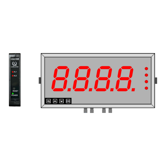
MAGNA 4-Digit Large-Digit
Temperature Indicator / Controller
Installation & Operating Manual
Caution: Risk of electrical shock if this instrument is not properly installed.
!
Caution: Read the whole manual before you install this display.
Rear case screws - please note
The rear panel is held in place with finger-screws, which
only need to be gently tightened.
Do not use tools to tighten or loosen the screws, as
this could cause damage to the internal threads.
LAUREL Electronics, Inc.
3183-G Airway Ave, Costa Mesa, CA 92626, USA
Tel +1 714-434-6131
www.laurels.com
Fax +1 714-434-3766
sales@laurels.com
1
Advertisement
Table of Contents

Related Manuals for LAUREL MAGNA


Summary of Contents for LAUREL MAGNA
- Page 1 MAGNA 4-Digit Large-Digit Temperature Indicator / Controller Installation & Operating Manual Caution: Risk of electrical shock if this instrument is not properly installed. Caution: Read the whole manual before you install this display. Rear case screws - please note The rear panel is held in place with finger-screws, which only need to be gently tightened.
-
Page 2: Warranty
In the event of a defect during the warranty period, the unit should be returned, freight (and all duties and taxes) prepaid by the Buyer to Laurel or to the authorized distributor from whom the unit was purchased. -
Page 3: Table Of Contents
Warnings Introduction General Description Connecting Your Display Suspension Mounting Dimensions Wall Mounting Dimensions Panel Mounting Dimensions MAGNA Connections 12-13 Temperature Display Connection Diagram Installation Hints for Best Performance Language Selection for User Interface Display Brightness Adjustment Meter Calibration Modes Direct Calibration - Full Scale Setting Direct Calibration - Zero setting Theoretical Calibration - Decimal Point &... -
Page 4: Warnings
Warnings Please carefully read this manual and all warnings. Install the display ONLY when you are sure that you’ve covered all aspects. Where the product is intended for “UL” installations, removal or addition of option boards is not permitted. Check that the model number and supply voltage suit your application before you install the display. -
Page 5: Introduction
Introduction Please contact us if you need help, if you have a complaint, or if you have suggestions to help us improve our products or services. If you contact us about a product you already have, please tell us the full model number and serial number, so that we can give you accurate and fast help. -
Page 6: General Description
General Description MAGNA temperature displays consists of a MAGNA 4-digit, 4-20 mA analog input large digit display and an external Laureate LT series RTD or thermocouple transmitter with a 4-20 mA analog output. Use of a 4-20 mA interface allows long cable runs while keept the thermocouple or RTD leads short. -
Page 7: Connecting Your Display
Connecting Your Display MAGNA temperature displays are shipped with an external Laurate LT temperature transmitter. As specified in the order, the transmitter will be set up for a specific RTD or thermocouuple type, for display in °C or °F, and for 1° or 0.1° resolution. 0.1° resolution should only be used for RTDs. - Page 8 Connecting Your Display (continued) Connect an RTD temperature signal to the transmitter as explained below, and run the 4-20 mA output of the transmitter trom P4-2 and P4-1 through an available gland. In 2-wire hookup, the meter senses the com- bined voltage drop across the RTD and both lead wires.
-
Page 9: Suspension Mounting Dimensions
Suspension Mounting Dimensions 15mmO 15mmO 6.35mmO 6.35mmO Plan View 25mm X mm Y mm Short-drop mounting holes Long-drop mounting holes W mm 77 mm H mm H mm 25mm Cable Glands. Number of glands depends on installed options. Detail showing bracket You can order these displays with the cable glands in the bottom surface (as shown) the hardware fitting sequence... -
Page 10: Wall Mounting Dimensions
Wall Mounting Dimensions 98 mm W mm 22mm 60 mm H mm 25mm Cable Glands. Number of glands depends on installed options. 80 mm 60 mm The 4 bracket holes are 5.2mm diameter 60 mm X mm 72.5 mm Detail showing bracket You can order these displays with the cable glands in the bottom surface (as shown) the hardware fitting sequence... -
Page 11: Panel Mounting Dimensions
Panel Mounting Dimensions 67mm 25mm H mm A mm Neoprene Bezel W mm gasket Neoprene Cable glands gasket B mm Detail showing bracket hardware fitting sequence Bezel Panel cutout dimensions Neoprene gasket Panel A+3mm(h) x B+3mm(w) M8 x 15 bolt Spring washer Fit first Flat washer... -
Page 12: Magna Connections
MAGNA Connections Warning: Disconnect all power before removing the rear of the display There is a range of possible locations for the input board, output board and power supply boards. Their locations depend on the height of digits, number of digits, brightness of digits and any installed options. - Page 13 MAGNA Connections Warning: Disconnect all power before removing the rear of the display Output option board (if fitted) Connectors and options Analog Connectors may be Serial Data 0, 2 or 4 Alarm Relay output present even if output output option...
-
Page 14: Temperature Display Connection Diagram
Temperature Display Connection Diagram... -
Page 15: Installation Hints For Best Performance
Installation Hints for Best Performance This section offers several suggestions which will help you get the best performance from your measurement system. Some sensors generate comparitively small signals which can easily be corrupted by the potentially high level of electrical noise which can be created by electrical machinery such as motors, welding systems, discharge lighting, AC power inverters and solenoids. -
Page 16: Language Selection For User Interface
Language Selection for User Interface Set1 Set2 Output Alarms Lockout Switch must be OFF Digit Max/Min Reset Circuit board Press together, briefly For 4 digits: for English Set1 Set2 Output Alarms Digit for French. Max/Min Reset (Default = English) Press to toggle Set1 Set2 Output... -
Page 17: Meter Calibration Modes
Meter Calibration Modes You can choose from two main calibration methods: 1. Direct Calibration - this is when you connect the meter to your system and make the meter read what you want it to, at two different points. This is the preferred calibration method, because it allows you to calibrate the system as a whole. -
Page 18: Direct Calibration - Full Scale Setting
Direct Calibration - Full Scale Setting This is when you connect the meter to your system and make the meter read what you want it to, at 2 different points. This is the preferred calibration method, because it allows you to calibrate the system as a whole. How to do direct calibration:- If you have not done so before, please select Direct Calibration mode from the previous page. -
Page 19: Direct Calibration - Zero Setting
Direct Calibration - Zero Setting How to calibrate the ZERO point. Set1 Set2 Output Alarms Lockout Switch must be OFF Digit Max/Min Reset Circuit board Press 3 seconds Set1 Set2 Output Alarms Apply the lowest calibration signal Digit you can achieve, ideally 0% of Max/Min Reset system capacity. -
Page 20: Theoretical Calibration - Decimal Point & Scale
Theoretical Cal. - Decimal Point & Full Scale This is when you type in the sensor’s theoretical signal level at the top and bottom of its range and the value to display, for each signal level. If you have not done so before, please select Theoretical Calibration mode from the Meter Calibration page AND choose whether your input is current or voltage. -
Page 21: Theoretical Calibration - Low End Calibration
Theoretical Calibration - Low End Calibration This is when you type in the sensor’s theoretical signal level at the top and bottom of its range and the value to display, for each signal level. If you have not done so before, please select Theoretical Calibration mode from the Meter Calibration page. -
Page 22: Sensor Drift Correction
Sensor Drift Correction The capability on this page is part of the MAGNA process display, but it is normally not used with temperature. If your system is normally reading 0, for example as is typical with platform scales or a torque meter, you may find a small amount of sensor drift caused by changes in temperature, ageing etc. -
Page 23: Logic Input Connection & Front Buttons
Logic Input Connections and Front Buttons The previous pages explained how to select the functions of the 3 logic inputs. You can connect remote contact closures or open NPN collectors to activate these logic inputs. The logic input provides a 5V DC signal. When you connect this to common, a current of 1mA will flow. -
Page 24: Factory Defaults
Factory Defaults You can return the display to its factory default conditions whenever you wish. If you do so, you will permanently loose all your settings and will need to start from the beginning again. The calibration Audit Counter will NOT be reset, there is no way provided to reset this value, as it is intended as a secure record to indicate whether changes have been made to the display since it was last calibrated.. -
Page 25: Signal Filtering / Averaging
Signal Filtering / Averaging You can adjust the filtering time constant to reduce the effect of noise or instability on your input signal. A larger FIL value will give a more stable display, but the response to signal changes will be slower. Because your output options, such as analogue output, alarm relays and serial output are all derived from the displayed value, they will respond at the same rate as the filtered display. -
Page 26: Filter Jump Value
Filter Jump Value The Filter Jump value allows you to decide how the display will respond to a process step change. It does this by overriding the filtering, if the input signal moves by more than a chosen amount in one conversion. The Filter Jump default value is 10%. This means that for noise amplitude which has a peak value of less than 10% of the input range, filtering will be applied. -
Page 27: Last Digit Rounding
Last Digit Rounding Up by 1, 2, 5, 10, 20 or 50 You can adjust the way the display rounds up, which is useful if you want to display a very large number, but do not want jitter on the last digit. The display can be set to round up to the nearest 1 (no rounding) 2, 5, 10, 20 or 50 Set1 Set2... -
Page 28: Scale Factor Adjustment
Scale Factor Adjustment After you have calibrated your meter, you can use the SCALE feature to make fine adjust- ments to calibration, without affecting the calibration itself. Example Changing volume units of measure from litres to Imperial gallons You could also use the SCALE to convert your readout from litres to imperial gallons, with- out affecting the calibration. -
Page 29: Offset Adjustment
Offset Adjustment After you have calibrated your meter, you can use the Offset feature to make fine additions or subtractions to the reading, without affecting the calibration itself. For example if your weighing structure is altered after calibration and you want to subtract the effect of 37kg of extra metalwork which was welded to the hopper, you can easily do this by entering a value of -37 in the offset value. -
Page 30: Menu Timeout Adjustment
Menu Timeout Adjustment The display has a default timeout of 60 seconds, to allow you sufficient time to refer to the manual between key operations. You can make this period shorter, if you wish, once you become more familiar with the setup method. -
Page 31: Reverse Dipslay Function (Mirror Image)
Reverse Display Function (Mirror Image) If you need to be able to see a reflection of the display in a mirror or other reflective surface, for example in a simple heads-up system, or for drivers reversing into a bay, using mirrors only, you can set the display to show as a mirror image. -
Page 32: Bootup Routine And Tare Save Choices
Bootup Routine and Tare Save Choices When you switch on your meter, it can be set to power up with 3 possible summary mes- sage combinations. The choices are:- (4 digits) = Segment test, followed by a full summary of software revision, calibration audit number, model number, installed options. -
Page 33: Error Codes And Fault Finding
Error Codes and Fault Finding 1. Under Range. The meter is being asked to display a value which is more negative than its limit of -1999 2. Over Range. The meter is being asked to display a value which is higher than its limit of 9999 These fault codes could be displayed because the signal is too negative, too positive, or because there is a wiring error, or because the display’s scaling... -
Page 34: Main Display Specifications
Main Display Specifications Case Material Heavy duty welded uPVC. Connectors Internal detachable Screw Terminal connectors accessed via compression glands. ° Environmental Storage Temperature range -20 to +70 C, non condensing. Operating temperature range 0 to 50C. Internal heater option ° available for use in conditions down to -25 Power 100-240 VAC, 48 VAC, 45 to 60Hz or 11-30 VDC optional. -
Page 35: Rtd Input Specifications
RTD Input Specifications Calibration, Pt 100 DIN Per IEC 751 (ITS-90) Calibration, Pt 100 ANSI NIST Monograph 126 Calibration, Ni 120 43760 Max error at 25°C, Pt100 ±0.04°C (±0.07°F) ±0.01% of reading Span tempco ±0.003% of reading/°C Zero tempco ±0.03 deg/deg Provision for user calibration Multiplier of RTD resistance plus offset in degrees Connection 2, 3 or 4-wire... -
Page 36: Thermocouple Input Specifications
Thermocouple Input Specifications Calibration NIST Monograph 125 (IPTS-68) Overall error at 25°C ±0.01% of full span ± conformity error Span tempco ±0.003% of reading/°C Reference junct. accuracy 0.5°C, 10°C to 40°C Input resistance 1 Gohm Input current 100 pA Max lead resistance 1 kohm max for rated accuracy Overvoltage protection 125 Vac... -
Page 37: Declaration Of Ce Conformity
Signal cabling shall be routed separately to power carrying cabling (includes relay output wiring) All signal cabling shall be screened. The screen shall only be terminated to the power earth terminal at the meter end of the cable. Declared as true and correct, for and on behalf of Laurel Electronics Ltd.
Need help?
Do you have a question about the MAGNA and is the answer not in the manual?
Questions and answers