
Summary of Contents for ANBTEK AS201E
- Page 1 GSM/GPS AS201E ’ USER S GUIDE ALARM RACKING Copyright © 2006-2015 Shenzhen ANB Technology Co., Ltd. All rights reserved.
-
Page 2: Table Of Contents
.3.2 Sleep Mode consumptions and how it works..................6 2.4 Transmitter Operation..........................7 .4.1 Transmitter Button functions ......................7 .4.2 Transmitter and wireless sensor Program to AS201E Box..............7 2.5 How to configure device (Configuration)....................8 .5.1 Configure by SMS commands ......................8 .5.2 Configure by PC tool “ AS201E Configurator” ................9 .6 I/O Introduction and Definition......................10... - Page 3 .16 Arm/Disarm Status LED Indicator .......................22 .17 Wireless Sensor Detection........................22 .18 Daily Travel Mileage SMS report to Driver ( A authorization Phone No.) ...........23 .19 OTA firmware .............................23 4. APPENDIX ..............................23 Copyright © 2006-2015 Shenzhen ANB Technology Co., Ltd. All rights reserved.
-
Page 4: Introduction
Introduction AS201E is a GSM/GPRS/GPS alarm tracking box for multi applications. This small unit is equipped with Quad Bands GSM/GPRS module, Hi-sensitivity GPS receiver and 3D Accelerometer. It’s also can be connected with optional wireless/wired accessories like fuel senor, RFID reader, iButton Probe Kit, Temperature senor, RF Key Fob, Alarm siren and Relay for external electronics device control. -
Page 5: Typical Application
Boats & Yacht 1.4 Package Contents 1.4.1 Standard Package Contents ) AS201E GPS Alarm Tracker x 1PC ) GSM Antenna x 1PC ) GPS Antenna x 1PC ) 18Pin Power+ I/O Wire harness x 1PC ) Panic Button x 1PC... -
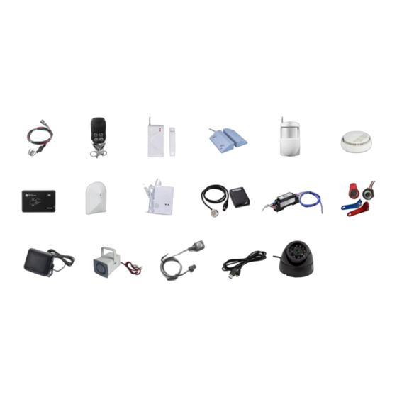
Page 6: Optional Accessories
2. Knowlege Before Usage 2.1 How it works? The AS201E mainframe works as a host box with multi input/outputs. The mainframe will process to get GPS location and various working status from inputs and wireless sensors, and then send those information to preset Phone Numbers or IP/Port Server via GSM network. -
Page 7: Factory Default Setting
2.3 Power Supply 2.3.1 External Power and Internal Power AS201E works with two power supply mode: External Power and Internal Battery. It's working normally with external power supply range from 9-36V DC. When the external power is disconnected or with low voltage output, device will switch to work on internal battery automatically. And it also will send"... -
Page 8: Transmitter Operation
In panic, Activate Siren to sound. Or in parking lot, press this button for car finding. 2.4.2 Transmitter and wireless sensor Program to AS201E Box If your transmitter is lost or damaged, or the transmitter battery is flat, the system can be overridden by Ignition switch conjunction with Panic Button. -
Page 9: How To Configure Device (Configuration)
For other wireless sensor, like Door/window contact, Smoke and gas detectors follow the same process to integrate them to system. 2.5 How to configure device (Configuration) AS201E box support configuration via SMS commands and also via PC program tool(Configurator) via connect AS201E with PC through USB cable. 2.5.1 Configure by SMS commands... -
Page 10: Configure By Pc Tool " As201E Configurator
2.5.2 Configure by PC tool “ AS201E Configurator” Connect AS201E with PC via USB cable: 2) Install CP2102 USB-Serial Driver: 3) Run AS201E configurator.exe and get into following interface: Copyright © 2006-2015 Shenzhen ANB Technology Co., Ltd. All rights reserved. -
Page 11: I/O Introduction And Definition
2.6 I/O Introduction and Definition Main I/O ports Introduction: I/O Pin slot Definition: L1 18Pin Port Pin slot definition: Wire Wire Color Function/Specification Description Pin No. Description Red/White Power positive pole, 9-36VDC Power Black/White Purple/White Over speed Buzzer(=0V,Effect) Yellow Siren/Hazard Light(12/24V, Effect) Lock Door(=0V, Effect) Blue Output... -
Page 12: How To Insert Simcard To As201E
If in Armed status, the system was disarmed, and get no Door open or Ignition status operation within 60 Seconds, system will automatic arm once. AS201E system allow user to enable/disarm Re-arm function according user’s usage habit. Re-Arm function Enable/Disarm Method:... -
Page 13: Remote Stop Oil/Power Supply For Engine (Immobilizer)
Alarm Siren Functionality Server Sound Shock alarm SMS Once SMS Once SMS Once 20Seconds Sound External Power SMS Once SMS Once SMS Once 20Seconds Sound Disconnection 20Seconds Sound Ignition ON SMS Once SMS Once SMS Once SMS Once Panic Alarm SMS Once SMS Once SMS Once... -
Page 14: Power Saving
In Armed status, the system will keep Oil/Power supply in locked status. This is to protect burglar ignore alarm alerts and start vehicle to drive away. This function is default as Disabled. If the user want to activate this function, can use SMS command sent AS201E inserted SIMCARD number to switch on and off this feature. - Page 15 Accident Alert for A/B/C Numbers By configure AS201E installation position and X,Y,Z axils value to setup the accident alert value limit as trigger conditions. AS201E provides two ways to configure: Configure By SMS commands *1234*CS*m,x.x,y.y,z.z# M for the custom direction value (1-6) x.x corresponding to X axis value (0.0-8.0)
-
Page 16: Voice Listen-In
Display accident data log via chart with time frame and G value varies: 3.6 Voice Listen-in Call Center Number D and SMS center Service No. G call AS201E, the system will put through to Voice Listen-in mode directly. AS201E also provide other two methods to start Voice listen-in Operation:... -
Page 17: Ibutton Probe Kit
3.8 iButton Probe Kit AS201E support 1-Wire iButton Key/Probe Kit for driver Identification, via the AS201E Configurator to set iButton Key , as following the picture : By SMS command, user can activate or close this feature: 1234*AUTHENIDON# <Driver Authorization Activated>... -
Page 18: Ultrasonic Fuel Senor Configure
How to install the Ultrasonic fuel senor please refer the < UF-141 Ultrasonic Fuel Sensor Installation Guide> provides two ways to configure: Set parameters by AS201E Configurator : How to activate the fuel senor on platform please refer the < UF-141 Ultrasonic Fuel Sensor Installation Guide>... -
Page 19: Asset Maintain Notice
This is to solve problem if any operation fail and do quick problem shooting. 3.15 Locate in parking Lot AS201E provides two methods for user to quick locate where the vehicle is by Siren sound and light flashing. . By press Remote controller Siren button to make sound . -
Page 20: Gps Tracking Features
3.16 GPS Tracking features 3.16.1 Real Time Tracking Track by SMS command 1234*FIND# <To query with Google Map link reply> 1234*GPS# <To query with GPRMC format GPS co-ordinates> Track by our GPS tracking platform First ,you need to configure IP/Port/APN to the device . Second , get a tracking account name and password.( Please contact your seller to got it) Copyright ©... -
Page 21: Speed Limit Manage
3.16.3 GEO Fencing Management AS201E maximum allows user to create 20 GEO fencing areas. And the area shape can be circular or rectangular. Considered text message only can contain 140Bytes text, so user need to create multi-areas with more than one text message command. -
Page 22: Emergency Medical/Information Call To Center(Two Way Intercom)
By Configurator program or SMS commands, user can configure one Call center Voice service Number D in AS201E. After the short call button was pressed, the AS201E will start to call this D number and connect to talk with Call center support people. -
Page 23: Mute Output Control For Original Car Radio
3.15 Mute Output control for Original car Radio This Mute output is for audio intercom purpose. When incoming call rings, AS201E will generate a signal to for this output cable and block Radio voice. The Mute signal output from AS201E I/O Port <L1 Pin12>... - Page 24 1234*ERASECODE*H# 3.18 Daily Travel Mileage SMS report to Driver ( A authorization Phone No.) AS201E designed to have a daily travel mileage SMS report to driver at defined time every day. Configure Mileage Report Time by SMS Command: *1234*REPTIME:09:36# <Set Mileage Report Time>...
Need help?
Do you have a question about the AS201E and is the answer not in the manual?
Questions and answers