Table of Contents

Summary of Contents for Jaspi GTV HYBRID 500
- Page 1 D103923 GTV HYBRID 500 ENERGY HEATER INSTALLATION OPERATING INSTRUCTIONS Manufacturer: KAUKORA OY www.jaspi.fi Tuotekatu 11, P.O. Box 21, 21201 RAISIO Tel. +358 20 2010 2010 (02) 4374 600, Fax (02) 4374 650 E-mail: kaukora@kaukora.fi...
-
Page 2: Table Of Contents
TABLE OF CONTENTS ACTION DESCRIPTION....3 TRANSPORT AND HANDLING ...... 4 TECHNICAL DATA AND DIMENSIONS ....5 DOMESTIC WATER CYCLES...... 6 SOLAR SPIRAL ....6 GENERAL INSTALLATION INSTRUCTIONS ...... 6 USE OF ELECTRICAL RESISTORS...... 6 PIPE INSTALLATION ...... 6 Illustration of the connection of the air-water heat pump........7 Illustration of the connection of the geothermal heat pump..... -
Page 3: Action Description
ACTIVITY DESCRIPTION The Jäspi GTV Hybrid 500 energy heater is suitable alongside all forms of energy, both heat pumps and traditional heating modes. Product design has been based on versatility, space friendliness and advanced energy economy. Hybrid accumulators are energy accumulators developed alongside low-temperature systems (e.g. heat pumps and solar energy) that provide heating of a waterborne floor and/or radiator system and hot water. -
Page 4: Transport And Handling
GTV Hybrid 500 with air-to-water heat pump GtV Hybrid 500 bookers also have a solar spiral as standard. It is therefore easy to switch to the utilisation of solar heat later on. You can find different models of the possibilities of utilising Jäspi Hybrid Accumulators at the internet address www.kaukora.fi. -
Page 5: Technical Data And Dimensions
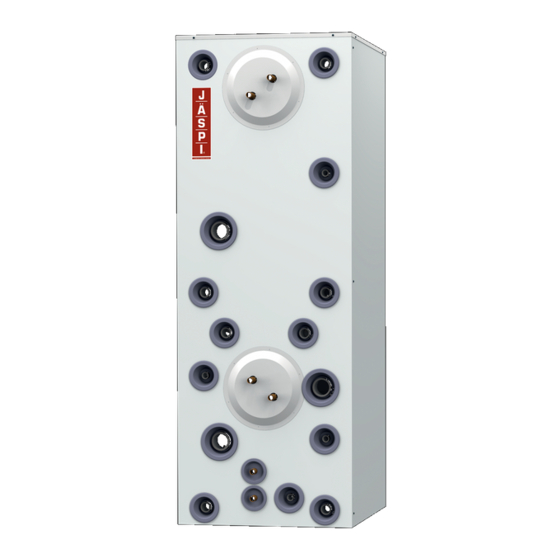
TECHNICAL DATA AND DIMENSIONS coil Baffle plate preheating coil Solar coil 2 Dimensions and sizes of joints Height: 1830 mm Width: 670 mm Depth: 680 mm Weight: 230 kg Maximum design pressure: 3 bar Maximum operating temperature: 110°C 5 / 16... -
Page 6: Domestic Water Cycles
DOMESTIC WATER CYCLES The heater has two 10m long ø 22mm combed copper coils when installed in factory. Coil type Flow (l/min) Power (kW) Program (58°C) LK 2 80 / 10- Total liquid volume of coils 6.2 litres Total external heat transfer area of the coils 5,1m² GTV 500 Hybrid,Domestic water output, Temperature at the top of the... -
Page 7: Illustration Of The Connection Of The Air-Water Heat Pump
Illustration of the connection of the air-water heat pump Jämä Moon switching image for installation on page 12. Illustration of the connection of the geothermal heat pump Jämä Earth heat pump switching images used for installation on pages 13-14. 7 / 16... -
Page 8: Illustration Of The Boiler Connection
Illustration of boiler connection Jäspi Double chamber boiler switching image for installation on page 15. Illustration of solar connection Jäspi Solar system switching image for installation on page 16. 8 / 16... -
Page 9: Illustration Of The Connection Of Domestic Water
Illustration of the connection of domestic water Switching images for installation on pages 12-16. Before commissioning, it must be ensured that the piping has undergone a leakage test and that the accumulator is full of water. The tank must be filled with water to avoid damage to any electrical resistors installed. -
Page 10: Guarantee
In example 2, 1.45 l is removed respectively. The examples are used to illustrate how much water expands as it heats up, and thus how much water can be removed through the safety valve in 24 hours. If this expanded part of the water cannot escape through the safety valve, the pressure in the system will rise so high that eventually the weakest point in the network will fail and cause water damage. - Page 11 11 out of 16...
- Page 12 12 out of 16...
- Page 13 13 out of 16...
- Page 14 14 out of 16...
- Page 15 15 out of 16...
- Page 16 D103923 We reserve the right to make changes © kaukora Oy 2015 D103923 r.1...
Need help?
Do you have a question about the GTV HYBRID 500 and is the answer not in the manual?
Questions and answers