Table of Contents
Advertisement
Quick Links
Advertisement
Table of Contents

Summary of Contents for 3scort Escort i-5
-
Page 2: Table Of Contents
2.9 Displaying total/average level of several TD sensors 2.10 Retransmission of BLE sensors data 2.11 Additional features (FW update, password management) 3 SERVICE AND SHELF LIFE, WARRANTY 4 TRANSPORTATION AND STORAGE 5 RECYCLING AND DISPOSAL 6 LINKS 7 CONTACTS ANNEX 1. Digital indicator Escort i-5: pinout... -
Page 3: General Information
‘listen’ the communication between a polling device and polled devices (such as wired sensors). Escort i-5 can transmit the data it receives from Escort BLE sensors via Bluetooth Low Energy interface to an external device once polled via the RS-485 or RS-232 interface. - Page 4 ESCORT. Digital indicator Escort i-5. User Manual 2022.08-05. Page 4 of 53 Wireless sensor/mobile device communication interface(s) Bluetooth LE (BLE) Wireless sensor and mobile device communication protocol(s) Escort BLE ESCORT.i-5 Bluetooth Low Energy 5 LR coded PHY (central) Bluetooth Standard...
-
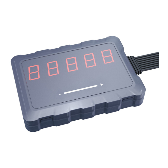
Page 5: Escort I-5 Design
ESCORT. Digital indicator Escort i-5. User Manual 2022.08-05. Page 5 of 53 1.3 Escort i-5 design Figure 1 demonstrates the design if the Escort i-5 indicator. Fig. 1 Escort i-5 design... -
Page 6: Scope Of Delivery
1.4 Scope of delivery The scope of delivery is indicated in the Table 2. Table 2. The kit contents Device designation: Ser.№ Note Digital indicator Escort i-5 User Manual ТЕМГ.468389.001 Digital indicator Escort i-5 Datasheet. To be specified while 468389.001 ПС ordering Installation kit ТЕМГ.416931.011:... -
Page 7: How To Use
Indicator will be clearly visible. Mount and fix the holder with the self-tapping screws. Place the Escort i-5 into the holder. Figure 3 demonstrates an example of the suggested installation. Figure 4 provides the fitting... -
Page 8: How To Connect I-5 Via App
ESCORT. Digital indicator Escort i-5. User Manual 2022.08-05. Page 8 of 53 Fig. 3 Approximate example of mounting the i-5 Fig. 4 Fitting dimensions 2.2 How to connect i-5 via app 2.2.1 Make sure that your smartphone supports BLUETOOTH LE (BLE 4.0 or higher) by checking its documents. - Page 9 ESCORT. Digital indicator Escort i-5. User Manual 2022.08-05. Page 9 of 53 Fig. 5 Start screen Fig. 6 Device model selection 2.2.4 When firing the app up for the 1st time, make sure to give it access to the geolocation service.
- Page 10 ESCORT. Digital indicator Escort i-5. User Manual 2022.08-05. Page 10 of 53 Fig. 8 Searching by the last 6 digits of the serial Fig. 7 List of available devices number...
- Page 11 User Manual 2022.08-05. Page 11 of 53 IMPORTANT! To activate the Escort i-5 and then to detect, connect and configure it by means of the app, be sure to connect it to a power supply. The wiring diagram is shown on the Fig 9.
-
Page 12: Password
ESCORT. Digital indicator Escort i-5. User Manual 2022.08-05. Page 12 of 53 2.2.6 After the i-5 is connected, it’s configuration is displayed on the screen (Fig. 10). At the top of the screen, you can see the device name and the current FW version (Fig. 10, 1). - Page 13 ESCORT. Digital indicator Escort i-5. User Manual 2022.08-05. Page 13 of 53 Fig. 11 Setting new password Fig. 12 Entering a previously set password 2.3.3 After setting the password and whenever you try and change any i-5’s settings, you will...
-
Page 14: Pairing Ble Sensors
ESCORT. Digital indicator Escort i-5. User Manual 2022.08-05. Page 14 of 53 2.4 Pairing BLE sensors 2.4.1 To pair any Escort BLE sensor (TD, DU, TH) you need to tap Connect sensors (Fig.13, 2). Then press the button to add a new sensor (Fig. 14). - Page 15 ESCORT. Digital indicator Escort i-5. User Manual 2022.08-05. Page 15 of 53 2.4.2 Then select the Wireless option and either enter the MAC or the sensor’s model letter and the last 6 digits of its serial number (Fig. 16) and press the ‘Connect’ button. Both MAC (Fig. 17, and Fig.
- Page 16 ESCORT. Digital indicator Escort i-5. User Manual 2022.08-05. Page 16 of 53 Fig. 17 MAC and serial number old design Fig. 18 MAC and serial number new design (DU-BLE used as an example) (TH-BLE used as an example)
- Page 17 ESCORT. Digital indicator Escort i-5. User Manual 2022.08-05. Page 17 of 53 2.4.3 After the sensor is connected you will see it on the main screen of the Indicator in the app (Fig. 19). Repeat the procedure to pair more sensors. Up to 10 sensors can be paired with the same i-5.
-
Page 18: Pairing Wired Sensors (No Tracker/Gateway)
ESCORT. Digital indicator Escort i-5. User Manual 2022.08-05. Page 18 of 53 2.5 Pairing wired sensors (no tracker/gateway) 2.5.1 If you need to connect your wired sensor(s) TD-100, TD-150, TD-500, TD-600, DGV-200, DU-180, ALS only to the i-5, i.e. there will be no GPS tracker or gateway to which the... - Page 19 ESCORT. Digital indicator Escort i-5. User Manual 2022.08-05. Page 19 of 53 2.5.3 Then select the ‘Wired’ option, enter the network address (the value can be from 0 to 255) and press ‘Connect’ (Fig. 23). If the i-5 is not configured to operate in the RS-485 Active mode or if there is no GPS tracker/gateway or other device that could request the data from the sensor so that the i-5 could listen to the sensor’s response and show its reading, the level of the wired sensor will be...
- Page 20 ESCORT. Digital indicator Escort i-5. User Manual 2022.08-05. Page 20 of 53 Fig. 25 Network address in the configurator for Fig. 26 Network address in the app (main screen and Settings screen) Attention! All wired sensors that are not the wired Escort TD sensors (such as DU-180, DGV-200, ALS or the wired sensors of other brands that support the LLS data communication protocol) will still be treated as the TD sensors.
- Page 21 ESCORT. Digital indicator Escort i-5. User Manual 2022.08-05. Page 21 of 53 2.5.6 To make the i-5 send requests for data to the wired sensor(s) connected to it, open the mode settings (Fig. 27, 4). The Passive mode is selected by default (Fig. 28).
- Page 22 ESCORT. Digital indicator Escort i-5. User Manual 2022.08-05. Page 22 of 53 2.5.7 Select the Active mode then enter the interval in seconds from 1 to 65 and press Set (Fig. 29). Then press Save to apply the changes (Fig. 30).
- Page 23 ESCORT. Digital indicator Escort i-5. User Manual 2022.08-05. Page 23 of 53 2.5.8 After the Active RS-485 mode is selected and the interval is set, you will see the readings of your wired sensor(s) in the app (Fig. 31, 32) if it was connected to the i-5 in accordance with the wiring diagram (Fig.
- Page 24 ESCORT. Digital indicator Escort i-5. User Manual 2022.08-05. Page 24 of 53 Fig. 33 Wiring diagrams: i-5 and wired sensor(s) (RS-485) no tracker/gateway...
-
Page 25: Pairing Wired Sensors (Tracker/Gateway Is Used)
ESCORT. Digital indicator Escort i-5. User Manual 2022.08-05. Page 25 of 53 2.6 Pairing wired sensors (tracker/gateway is used) 2.6.1 If you need to connect the i-5 between a GPS tracker/gateway (or other compatible device) and a wired sensor (or several sensors), you need to connect the sensor as shown on the wiring diagram below, pair the sensor with the indicator and configure the Indicator i-5 to operate in the RS-485 Passive mode (the default mode). - Page 26 ESCORT. Digital indicator Escort i-5. User Manual 2022.08-05. Page 26 of 53 2.6.3 Then select the ‘Wired’ option, enter the network address (the value can be from 1 to 255) and press ‘Connect’ (Fig. 36). If the i-5 is not configured to operate in the RS-485 Active mode or if there is no GPS tracker/gateway or other device that could request the data from the sensor so that the i-5 could listen to the sensor’s response and show its reading, the level of the wired sensor will be...
- Page 27 ESCORT. Digital indicator Escort i-5. User Manual 2022.08-05. Page 27 of 53 Fig. 38 Network address in the configurator for Fig. 39 Network address in the app (main screen and Settings screen) Attention! All wired sensors that are not the wired Escort TD sensors (such as DU-180, DGV-200, ALS or the wired sensors of other brands that support the LLS data communication protocol) will still be treated as the TD sensors.
- Page 28 ESCORT. Digital indicator Escort i-5. User Manual 2022.08-05. Page 28 of 53 2.6.6 If the Indicator i-5 is connected “between” the wired sensor(s) and the GPS tracker/gateway or other compatible device, its operating mode must be the Passive one. To select it, open the mode settings (Fig.
- Page 29 ESCORT. Digital indicator Escort i-5. User Manual 2022.08-05. Page 29 of 53 2.6.7 If the sensor is connected to the tracker and the tracker is receiving the data from it and the Indicator is connected in accordance with the wiring diagram (Fig. 44), you will see the sensor’s readings in the app as well (Fig.
- Page 30 ESCORT. Digital indicator Escort i-5. User Manual 2022.08-05. Page 30 of 53 Fig. 44 Wiring diagrams: i-5, wired sensor(s) (RS-485) and tracker/gateway...
-
Page 31: Tank Calibration Table For Td-Ble
ESCORT. Digital indicator Escort i-5. User Manual 2022.08-05. Page 31 of 53 2.7 Tank calibration table for TD-BLE 2.7.1 If you just pair BLE or wired TD sensors with the Indicator i-5, the latter will be displaying the level values from 1 to 1023 or from 1 to 4095. In order to get the Indicator display the liters/gallons, you need to save a tank calibration table in the i-5’s memory for every TD sensor. - Page 32 ESCORT. Digital indicator Escort i-5. User Manual 2022.08-05. Page 32 of 53 2.7.3 Next, you can either import the table from the file saved on your smartphone or enter the table manually. To do so, open the sensor’s configuration and tap Start tank calibration (Fig. 47, 1).
- Page 33 ESCORT. Digital indicator Escort i-5. User Manual 2022.08-05. Page 33 of 53 Fig. 49 Searching table file Fig. 50 Table added. Press Save...
- Page 34 ESCORT. Digital indicator Escort i-5. User Manual 2022.08-05. Page 34 of 53 2.7.5 You can modify the table if you press any cell (Fig. 51). Also, you can set the Portion (in liters/or gallons) and then add new lines to the table (Fig. 52). To delete any line, press and hold it then swipe to the left and tap Delete (Fig.
- Page 35 ESCORT. Digital indicator Escort i-5. User Manual 2022.08-05. Page 35 of 53 Fig. 53 Deleting lines from table 2.7.6 To enter the table manually, select the corresponding option on the screen shown on the Figure 48, then set the portion (Fig. 52), add as many portions as you need and edit the level values as per the table you have and need to upload into the Indicator’s memory (Fig.
- Page 36 ESCORT. Digital indicator Escort i-5. User Manual 2022.08-05. Page 36 of 53 Fig. 54 Enabling tank calibration table Fig. 55 Checking the currently saved table (2) and checking the currently saved table (swipe downwards to see the whole table)
-
Page 37: Configuring Indicator's Screen
ESCORT. Digital indicator Escort i-5. User Manual 2022.08-05. Page 37 of 53 2.8 Configuring Indicator’s screen 2.8.1 Once all sensors are paired with the Indicator i-5, you need to configure what data will be displayed on its physical screen. 2.8.2 There are 10 virtual Windows that you can switch between by pressing the buttons of the indicator. - Page 38 ESCORT. Digital indicator Escort i-5. User Manual 2022.08-05. Page 38 of 53 B – the reading of the sensor connected to the Window 1 that appears in a few seconds 2.8.3 To activate one of the Windows 1-10 (Fig. 57, 1), you need to switch it on in the settings of the Indicator and select the sensor whose data will be displayed in the Window X (Fig.
- Page 39 ESCORT. Digital indicator Escort i-5. User Manual 2022.08-05. Page 39 of 53 2.8.4 For TD sensors (both BLE and wired ones, as well as the wired DU-180, DGV-200, ALS) select the Level reading in the Screen mode menu. Then select the sensor whose data must be displayed in the selected Window X in the Sensors menu (Fig.
- Page 40 ESCORT. Digital indicator Escort i-5. User Manual 2022.08-05. Page 40 of 53 2.8.5 If there are several sensors of different models that transmit the same data type (for example, Temperature), you will also need to select the sensor whose data must be displayed on the Indicator’s screen when the corresponding Window is selected by pressing the buttons.
-
Page 41: Displaying Total/Average Level Of Several Td Sensors
ESCORT. Digital indicator Escort i-5. User Manual 2022.08-05. Page 41 of 53 2.9 Displaying total/average level of several TD sensors 2.9.1 If you have several sensors installed on the same vehicle and in the same tank and you need the Indicator i-5 to show their average value, go to the Display settings (Fig. 62, 3) choose one of the Windows 1-10 in the Display settings menu and select the TD average level in the Screen mode (Fig. - Page 42 ESCORT. Digital indicator Escort i-5. User Manual 2022.08-05. Page 42 of 53 2.9.2 If you have several sensors installed on the same vehicle but in different tanks and you need the Indicator i-5 to show their total value, choose one of the Windows 1-10 in the Display settings (Fig.
- Page 43 ESCORT. Digital indicator Escort i-5. User Manual 2022.08-05. Page 43 of 53 2.9.3 In order to include a particular TD sensor (BLE or wired one) into the total/average calculation, go to the Connect sensors (Fig. 66, 2) and tap on the sensor you need (Fig 67). Then switch the Include in total/average calculation tumbler on (Fig 68, 3).
-
Page 44: Retransmission Of Ble Sensors Data
ESCORT. Digital indicator Escort i-5. User Manual 2022.08-05. Page 44 of 53 2.10 Retransmission of BLE sensors data 2.10.1 The Indicator i-5 can retransmit the data it receives from the paired Escort BLE sensors (TD, TH, DU) to an external device (GPS tracker/gateway/other compatible device) via the RS-485 interface. - Page 45 ESCORT. Digital indicator Escort i-5. User Manual 2022.08-05. Page 45 of 53 Fig. 71 Press on the pair of parameters you need transmitted Fig. 72 Select network address and press Save 2.10.3 Select the pair of parameters you need transmitted and switch that pair on (Fig. 71).
- Page 46 ESCORT. Digital indicator Escort i-5. User Manual 2022.08-05. Page 46 of 53 2.10.4 The wiring diagram (Fig. 73) demonstrates how to connect the Indicator i-5, wired sensor(s) and an external device by means of the RS-485 interface. It is possible to use the i-5 in the...
-
Page 47: Additional Features (Fw Update, Password Management)
ESCORT. Digital indicator Escort i-5. User Manual 2022.08-05. Page 47 of 53 2.11 Additional features (FW update, password management) 2.11.1 If you need to set up, modify or delete the password, go to the Additional features (Fig. 74, 5) menu. If there is no password yet, you will be able to establish it. If there’s a password, you can modify or delete it by entering the currently established password and then delete it. - Page 48 ESCORT. Digital indicator Escort i-5. User Manual 2022.08-05. Page 48 of 53 Fig. 76 FW update start.
-
Page 49: Service And Shelf Life, Warranty
Over the course of the Device’s service life, the manufacturer is obliged to repair or replace the Digital indicator Escort i-5 without any additional payment. In such case, the warranty terms stated in the Datasheet and/or User Manual of Device shall not be changed, edited or modified. - Page 50 ESCORT. Digital indicator Escort i-5. User Manual 2022.08-05. Page 50 of 53 3.6 The manufacturer reserves the right to make changes in the Device’s design and in its scope of delivery without prior notice to the customer.
-
Page 51: Transportation And Storage
ESCORT. Digital indicator Escort i-5. User Manual 2022.08-05. Page 51 of 53 4 TRANSPORTATION AND STORAGE 4.1 The Device must be transported in a sealed box or other packaging of the manufacturer’s choice. 4.2 The Device, once packed by the manufacturer, can be transported by means of vehicles, trains or air craft over any distances provided that the device is well protected against dirt, precipitations and strong vibrations during the transportation as per the requirements of the ГОСТ... -
Page 52: Recycling And Disposal
User Manual 2022.08-05. Page 52 of 53 5 RECYCLING AND DISPOSAL 5.1 The Digital indicator Escort i-5 shall be disposed of by the customer in accordance with the regulations applicable in the Russian Federation. 5.2 The Device does not contain any hazardous materials. -
Page 53: Annex 1. Digital Indicator Escort I-5: Pinout
ESCORT. Digital indicator Escort i-5. User Manual 2022.08-05. Page 53 of 53 ANNEX 1. Digital indicator Escort i-5: pinout...
Need help?
Do you have a question about the Escort i-5 and is the answer not in the manual?
Questions and answers