Table of Contents
Advertisement
Quick Links
Advertisement
Table of Contents

Summary of Contents for DIGIWAY PTY SW50-2
- Page 1 DIGIWAY PTY LTD SW50-2 Dual Swing Gate Motor INSTRUCTION MANUAL - 1 -...
-
Page 2: Important Safety Warning
IMPORTANT SAFETY WARNING Electricity and power motors associated accessories could be fatal or at least cause seriously injury. Digiway suggested some safety device to be used so as to prevent personnel from being injured by motorized device being controlled. All main voltage wiring must be installed by a licensed electrician. -
Page 3: Main Features
MAIN FEATURES 1. General Descriptions and features General descriptions It is recommended reading and understanding this manual before start to install the control board. Some features and idea are new. So, take some time to read through the manual to get better understanding of the board. -
Page 4: Closed Position
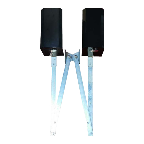
GATE MOTOR MOUNTING Closed Position Opened position Standard installation for brick post Closed Position Opened position Gate Swing in - 4 -... - Page 5 Closed Position Opened position Gate swing in Opened position Closed Position Brick Post, Gate Swing Out - 5 -...
- Page 6 Opened position Closed Position Steel Post, swing out application Closed Position Opened position Steel Post, small side room, swing in with special parts - 6 -...
- Page 7 Closed Position Opened position Special limited side room, cut the arm to suit the application - 7 -...
-
Page 8: Manual Release
Manual Release 1) Anticlockwise push handle. 2) push handle to the position. 3) Push motor up and left direction. NOW GATE IS FREE TO MOVE. 4) Push motor down and right direction. Make sure gears engaged. 5) push manual release handle clockwise and clock the gear. - 8 -... - Page 9 GATE MOTOR CONTROLLER 3. Control board The SW50-2 swing gate motor controlled by DC2 control board, which has following features: • Control one or two 12 or 24V DC motors. For Swing gates, Sliding Gates, Roller shutter doors etc. •...
- Page 10 GATE MOTOR CONTROLLER 1. OPN open push button 2. CLS close push button 3. PED pedestrian open push button 4. OSC Open, Stop, Close push button 5. Gate status display, open green, close red 6. Mode selection DIP switch 7. Close motor force (reverse power) 8.
-
Page 11: Controller Settings
CONTROLLER SETTINGS Control Terminals OPN ----- N/O open input. PED ------ N/O pedestrian open push button, only open motor-1 PEB ------ N/C photo electrical beams OSC------ N/O Open – Stop – Close--Open OL1 ------ Motor 1 open limit switch, N/C or N/O selected by DIP4 CL1 ------ Motor 1 close limit switch, N/C or N/O selected by DIP4 OL2 ------ Motor 2 open limit switch, N/C or N/O selected by DIP4 CL2 ------ Motor 2 close limit switch, N/C or N/O selected by DIP4... -
Page 12: Controller Setting
Controller Setting Set time settings Turn SET on, red and green LED flashes a little fast alternatively. Push and hold on OPN for Sync Delay Time Push and hold on PED for Lock Pulse Time Push and hold on CLS for PE Trig Close Time Push and hold on STP for Auto Close Time Factory setting Timer... -
Page 13: Motor Connection
MOTOR CONNECTION 4 Motor Connections 4.1 Two wires motor without limit switch 4.2 Five wires motor with N/C limit switch - 13 -... - Page 14 4.3 Sample of five wires with N/C limit 4.4 Step by step set up motor. a) Mounting and connect motor b) Disengage cutch and push two gates in middle position, then engage clutch. Power up, push OPN button, gate should open, if any gate goes close direction, switch motor two wires.
-
Page 15: Troubleshooting Guide
TROUBLE SHOOTING GUIDE 5 Trouble shooting guide 5.1 General checking Normally if installation is done properly, there would be trouble free. If in case of malfunction, please checking as following steps. 1) Check the DIP setting limit switch selection is right. 2) Gate status LED green (open) and red (close), one or both should be flashing depending on the gate position.
Need help?
Do you have a question about the SW50-2 and is the answer not in the manual?
Questions and answers