
Related Manuals for weschler instruments OMBGP100


Summary of Contents for weschler instruments OMBGP100
- Page 1 ACP4 BarGraph Watt & Var Meters Owners Manual Manual Part Number OMBGP100 Revision 1, June, 2006 16900 FOLTZ PARKWAY, CLEVELAND, OHIO 44149 440/238-2550, FAX 440/238-0660 e-mail: sales@weschler.com...
-
Page 2: Table Of Contents
Table of Contents Title Section Page Introduction ........1.0 ........1 Description Intended Usage Models and Features... - Page 3 By programming the four set point values, the bar may be set to change colors at different measured signal magnitudes, insuring that operators are instantly aware of operation within or outside of normal boundaries, without reading the actual value. OMBGP100 Rev 1 Page 1 of 23...
-
Page 4: Display And Controls
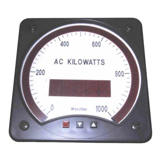
Alarm 4 LoLo Annunciator Alarm 1 HiHi Annunciator 4 ½ Digit Numeric Display Enter / Save Button Increment Button Decrement Button Figure 2. Enhanced and TriColor ACP4 BarGraph Dial and Front Panel Features OMBGP100 Rev 1 Page 2 of 23... -
Page 5: Terminal Assignments
Connectors are Phoenix-Type. Plugs are Furnished if These Options are Ordered. Communications Wiring Terminal RS-232 RS-485 #6-32 Screw Terminals Wickman type 374/TR5 Time Lag Fuse. Note relationship of pins to the line marked on the fuse body. OMBGP100 Rev 1 Page 3 of 23... - Page 6 0 and 24 ma corresponding to any on-scale signal span. The output is not bipolar, however; if can only produce positive current values. On both output types, 20 to 24 AWG, 300 volt, 105 EC hook up wire is recommended. OMBGP100 Rev 1 Page 4 of 23...
-
Page 7: Relay Contact Ratings
All other instruments in the BarGraph ACP4 series draw less current. It is recommended that the external wiring be 20 AWG or greater diameter with a 600 volt, 105 EC insulation rating. Consult national and local wiring standards for actual wiring requirements. OMBGP100 Rev 1 Page 5 of 23... -
Page 8: Interfacing A Pc For Rs-485 Communications With Multiple Bargraphs
ID, selected from a range of 00 to 99 hex (153 decimal). Note that the BarGraph display shows unit ID's as decimal numbers, but the actual protocol uses hex numbers. The decimal number shown on the display must therefore be converted to hex in order for the host to correctly address the BarGraph. OMBGP100 Rev 1 Page 6 of 23... -
Page 9: Signal Connections (5A - 5J)
Figure 5F. 3 Phase 4 Wire Type Figure 5E. 3 Phase 3 Wire Type BGP Wattmeter and BGV BGP Wattmeter and BGV Varmeter BGP Wattmeter and BGV Varmeter with Molded Base with Molded Base Varmeter with Molded Base OMBGP100 Rev 1 Page 7 of 23... - Page 10 The following connections are less common, but are supported by APP-4 BarGraphs: Figure 5J. 3 Phase 4 Wire, 3 PT Figure 5I. 3 Phase 4 Wire, 3 PT Types BGP & BGV Wattmeter & Type BGV Varmeter Varmeter with Molded Base OMBGP100 Rev 1 Page 8 of 23...
-
Page 11: Jumper Locations
BGG/BGP/BGV 251 & 281 BGG/BGP/BGV-241 Jumper JA1 BGG/BGP/BGV 261 Jumper JA1 Position Unused Numeric Display Flash Inhibit (stops flashing of numeric display only) Jumper Block JA2 Numeric and Bar Display Flash Inhibit Lamp Test OMBGP100 Rev 1 Page 9 of 23... - Page 12 When referred to set point operation, hysteresis is the magnitude, or amount, that a process value must retreat from an alarm condition, to cause the alarm to reset. After choosing an option value, be sure to press the enter button to save the choice. OMBGP100 Rev 1 Page 10 of 23...
- Page 13 (set bar full scale) functions. The bZr function is used to specify the left end scale in absolute signal value and the bFL function is used to specify the right end scale in absolute signal value. OMBGP100 Rev 1 Page 11 of 23...
- Page 14 (IED) on a communications cable with multiple connected IED’s. The ID number can be of any value between 0 (default) and 255. OMBGP100 Rev 1 Page 12 of 23...
-
Page 15: Supervisor Mode Configuration Keystroke Diagram (7A & 7B)
This is a calibration function. Do not disturb settings unless you are fully 0000.0 prepared to perform a full calibration. See the calibration section 6 for details. This function provides a means of setting up the bar display’s response to signal inputs. FROM OMBGP100 Rev 1 Page 13 of 23... - Page 16 Dawn, mixed one table spoon of detergent to one quart of water. Wipe the window area with another cloth dampened with clear water to rinse off any remaining detergent. Avoid getting water into the button holes of the BarGraph. OMBGP100 Rev 1 Page 14 of 23...
-
Page 17: Operator Mode Keystroke Diagram
If no button activity has been logged for 45 seconds, the BarGraph willl revert to normal operation. While in operator mode, all background processes, including alarm operation, communications and analog retransmit continue to function normally. Changes to alarm values will take effect after resuming normal operation. OMBGP100 Rev 1 Page 15 of 23... -
Page 18: Single Phase Test Connections
1. Connect the BarGraph potential circuits in parallel and the current circuits in series as shown in figure 9. Polarity is indicated by the “ ± “ character. Figure 9. Single Phase Test Connections OMBGP100 Rev 1 Page 16 of 23... - Page 19 14. Re-check left and right end scale indications using the above steps, without pressing any programming buttons. 15. De-energize the calibration circuit and turn off the test equipment and the BarGraph. Replace the BarGraph cover and return it to service. OMBGP100 Rev 1 Page 17 of 23...
-
Page 20: Fuse Ratings (3A Standard, 3B Enhanced, 3C Tricolor)
4300000313 “ 374-0800-041 125 vdc 4300000311 “ 374-0500-041 250 vdc 0.25 4300000308 “ 374-0250-041 120 vac 4300000311 “ 374-0500-041 240 vac 0.25 4300000308 “ 374-0250-041 Universal 4300000311 “ 374-0500-041 120 vac / 125vdc OMBGP100 Rev 1 Page 18 of 23... -
Page 21: Connection Error Symptoms (4A- 3P 3W; 4B- 3P 4W)
Phase currents are switched to wrong Correct current terminal connections terminals. Indication is ½ expected value. One of the potential or current circuits Check and correct connections. is connected to the BarGraph’s phase B terminals. OMBGP100 Rev 1 Page 19 of 23... - Page 22 If magnitude and polarity become correct, mark all connections OK. If polarity becomes correct but magnitude is still incorrect, mark this connection as OK. Reverse the next phase connection. Polarity and magnitude should now be correct. OMBGP100 Rev 1 Page 20 of 23...
-
Page 23: 8.0 Specifications
± 10% 1.3 VA 12.3 VA “ Univ. 110vac/dc-250vac/dc 85-264vac/100-300vdc 3 VA / 35ma 11.5VA / 65ma 50-60 Hz / NA Notes: Condensing conditions are allowed provided the conformal coating option is ordered. OMBGP100 Rev 1 Page 21 of 23... -
Page 24: Outline, Cutout And Drilling (3A - 3C)
Figure 10A. BGG-BGP-BGV 241 Cutout and Drilling Diagram Figure 10B. BGG-BGP-BGV 261Cutout and Drilling Diagram OMBGP100 Rev 1 Page 22 of 23... - Page 25 All Weschler Instrument’s ACP4 BarGraphs are warranted against defects in material and workmanship for a period of two years from date of delivery. Weschler Instruments, at its option, will repair or replace any defective product returned to it during the warranty period without charge, provided there is no evidence that the equipment was mishandled or abused.
Need help?
Do you have a question about the OMBGP100 and is the answer not in the manual?
Questions and answers