Table of Contents
Advertisement
Quick Links
Advertisement
Table of Contents

Related Manuals for Wahuda 50180CC-WHD

Summary of Contents for Wahuda 50180CC-WHD
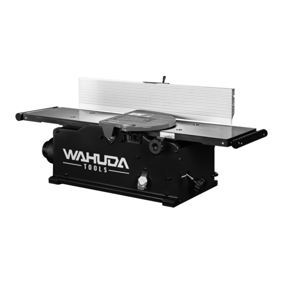
- Page 1 User Manual Read this manual before using machine to avoid serious injury and damage 50180CC-WHD 8” Bench Top Jointer with Spiral Style Cutterhead 4-Sided Carbide Inserts and Cast Iron Tables For technical support, email or call 877-568-8879 techservices@wahudatools.com VER 04.26.22 (C)
-
Page 2: Table Of Contents
The drawings, illustrations, photographs, and specifications in this user manual represent your machine at time of print. However, changes may be made to your machine or this manual at any time with no obligation to WAHUDA. -
Page 3: Warranty
2 YEAR LIMITED WARRANTY WAHUDA warrants its machinery to be free of defects in workmanship and materials for a period of two (2) years from the date of the original purchase by the original owner. This warranty applies to products sold in United States only. The warranty does not apply to any product used for professional or commercial production purposes nor for industrial or educational applications. -
Page 4: Product Specifications
PRODUCT SPECIFICATIONS Cutterhead speed RPM 12,000 Motor RPM 19000+/-10% (No Load) Cutterhead diameter 2" Max width capacity 8" Max depth of cut 1/8” Cutter inserts qty Motor power input 120 V, 60 Hz, AC Only, 10 Amp Fence Size Overall 4 ⅜"... -
Page 5: General Safety
GENERAL SAFETY NOTE: The WARNING! and CAUTION! symbols indicate a potentially hazardous situation which, if not avoided, COULD result in death or serious injury. READ THIS MANUAL completely before assembling and operating this machine. WARNING! TO AVOID serious injury, death, or damage to the machine, please read, understand, and follow, all Safety and Operating Instructions before assembling and operating this machine. - Page 6 GENERAL SAFETY (cont.) ALWAYS keep the work area clean, well lit, and organized. DO NOT work in an area that has slippery floor surfaces from debris, grease, and wax. CAUTION! ALWAYS unplug the machine from the electrical receptacle when making adjustments, changing parts or performing any maintenance.
- Page 7 GENERAL SAFETY (cont.) KEEP protective guards in place and in working order. CAUTION! MAINTAIN your balance. DO NOT extend yourself over the tool. Wear oil resistant rubber soled shoes. Keep floor clear of debris, grease, and wax. MAINTAIN all machines with care. ALWAYS KEEP machine clean and in good working order. KEEP all blades and tool bits sharp.
-
Page 8: Product Safety
WARNING! DO NOT handle the plug or jointer with wet hands USE only accessories as described in this manual and recommended by WAHUDA. 10. DO NOT pull the jointer by the power cord. NEVER allow the power cord to come in contact with sharp edges, hot surfaces, oil or grease. - Page 9 PRODUCT SAFETY (cont.) 14. ENSURE that the machine sits firmly before using. If the machine wobbles or is unstable, correct the problem by attaching to a bench top prior to operation. 15. This machine is designed to process wood ONLY. WARNING! NEVER position fingers or thumbs near the cutterhead.
-
Page 10: Grounding Instructions
GROUNDING INSTRUCTIONS WARNING! This machine MUST BE GROUNDED while in use to protect the operator from electric shock. In the event of a malfunction or breakdown, GROUNDING provides the path of least resistance for electric current and reduces the risk of electric shock. The plug MUST be plugged into a matching electrical receptacle that is properly installed and grounded in accordance with ALL local codes and ordinances. - Page 11 GROUNDING INSTRUCTIONS (cont.) Make certain the extension cord is properly sized, and in good electrical condition. Always replace a worn or damaged extension cord immediately or have it repaired by a qualified person before using it. Protect your extension cords from sharp objects, excessive heat, and damp or wet areas. MINIMUM RECOMMENDED GAUGE FOR EXTENSION CORDS (AWG) 115 VOLT OPERATION ONLY 25’...
-
Page 12: Unpacking & Inventory
NOTE: Some parts pictured may already be installed on your machine at the factory. Please go through the entire manual before contacting WAHUDA. Compare the items to inventory figures and verify that all items are accounted for. If any parts are missing, do not attempt to power on the machine. -
Page 14: Assembly & Adjustments
ASSEMBLY & ADJUSTMENTS WARNING! MAKE CERTAIN THAT THE MACHINE IS DISCONNECTED FROM THE POWER SOURCE BEFORE ASSEMBLY AND ADJUSTMENTS FENCE ASSEMBLY PROCEDURE 1. Face the rear of the jointer and remove the 4 screws (A) using the provided 4mm Hex Wrench. See FIG 1 2. - Page 15 ASSEMBLY & ADJUSTMENTS (cont.) 3. Locate the Fence Sliding Bracket (See page 13) and the 2 screws and 2 square nuts (See page 13). Insert screws through the Fence Sliding Bracket upper holes “A” in FIG 3, and thread the square nuts on by hand about 3 compete turns. See FIG 4. Do not tighten at this time.
- Page 16 ASSEMBLY & ADJUSTMENTS (cont.) 4. Locate Fence (See page 13) and slide from end, with the back of fence facing bracket, over the square nuts as shown in FIG 5. Note that the bottom of the fence is beveled and the square nuts have flats on them so you may have to rotate them slightly to slide the fence on.
- Page 17 ASSEMBLY & ADJUSTMENTS (cont.) 6. Facing the rear of the jointer, place the Sliding Bracket Fence Assembly onto the Fence Bracket and slide forward (towards front of the jointer) until the table holes are half exposed as shown in FIG 7. 7.
- Page 18 ASSEMBLY & ADJUSTMENTS (cont.) CUTTERHEAD GUARD The cutterhead guard has a tension return spring. The tension on this spring is set at the factory. When the guard is installed properly it should return to the fence automatically after the work piece has passed over the cutterhead. Be sure the guard is functioning properly every time before using the jointer.
- Page 19 ASSEMBLY & ADJUSTMENTS (cont.) FENCE ADJUSTMENTS The fence can be tilted from 90 to 135 degrees. There are 2 adjustable stop set screws for these limits. See FIG 17 for the location of these set screws. 1. To set the 90 degree stop, slightly loosen fence lever “B”, which locks the fence in place, and lift fence slightly clearing tables and slide fence forward approximately 1 inch.
- Page 20 ASSEMBLY & ADJUSTMENTS (cont.) 2. To set the 135 degree stop, slightly loosen lever “B” and loosen fence lever “A”. Slide the fence back completely and re-tighten lever “A”. Place a 45 degree angle against the fence, insert shims under fence, and use the provided 2.5mm Hex Wrench to adjust the 135 degree set screw against the stop.
-
Page 21: (Optional) Cleaning Spiral Cutterhead & Tips
POWER SOURCE BEFORE PERFORMING ANY MAINTENANCE PROCEDURES NOTE: WAHUDA spiral cutterheads are machined with a film of oil that may be left over from the process. Run pieces of scrap to remove the residue if apparent. If residue is still present after machining scrap, only then perform the following procedures. - Page 22 CLEANING SPIRAL CUTTERHEAD & TIPS (cont.) Step 3 - Separate the tips from the screws and place in separate containers with a bit of mineral spirits or non-chlorinated brake cleaner. Once all are removed, wipe down the bare cutterhead using rags with whichever solvent you chose. Once the oil is wiped off, use an air compressor or a can of pressurized air to clear each seat and screw hole on the cutter head.
-
Page 23: Operations
OPERATIONS NOTE: USE SCRAP STOCK TO FIRST TO CHECK JOINTER SET UP AND OPERATIONS. ONCE YOU HAVE DESIRED RESULTS, ONLY THEN USE YOUR PROJECT STOCK NOTE: This operations section was designed to give instructions on the basic operations of this jointer. - Page 24 OPERATIONS (cont.) DIRECTION OF GRAIN Avoid feeding work into the jointer against the grain. The result will be chipped and splintered edges or tear out. Feed with the grain to obtain a smooth surface. See FIG 25 FIG 25 The jointer can be set to cut any depth from a very thin shaving to 1/8” deep. The pointer on the scale is to indicate the depth of cut.
- Page 25 OPERATIONS (cont.) PLACEMENT OF HANDS DURING FEEDING At the start of the cut, the left hand holds the work against the infeed table and fence, while the right hand pushes the work down and toward the knives. After the cut is underway, the new surface rests on the outfeed table.
- Page 26 OPERATIONS (cont.) JOINTING AN EDGE This is the most common operation for the jointer. These cuts are made to square an edge of a work piece that already has one flat face to rest against the fence. Set the fence square with the table.
- Page 27 OPERATIONS (cont.) UNDESIREBALE RESULTS NOTE: Rough sawn , bowed, cupped, or twisted stock will take several passes before a smooth finish is achieved. Apply light downward pressure to this type of stock and take very shallow depth of cut passes to eliminate stock waste and bowed surfaces. Research proper jointing methods for imperfect lumber.
-
Page 28: Maintenance
MAINTENANCE WARNING! MAKE CERTAIN THAT THE MACHINE IS DISCONNECTED FROM THE POWER SOURCE BEFORE PERFORMING ANY MAINTENANCE PROCEDURES Your jointer should provide you with a long time of service provided you take the time to perform the following maintenance operations. CLEANING Sawdust buildup and other debris can cause the tool to joint and plane incorrectly. - Page 29 MAINTENANCE (cont.) WARNING! MAKE CERTAIN THAT THE MACHINE IS DISCONNECTED FROM THE POWER SOURCE BEFORE PERFORMING ANY MAINTENANCE PROCEDURES CUTTER TIP REPLACEMENT – USE PAGES 21 - 22 FOR REFERENCE IF NECESSARY WARNING: To prevent serious personal injury NEVER rotate the cutterhead by hand. Cutter tips are razor sharp! Always wear heavy leather gloves when handling the cuttherhead.
- Page 30 MAINTENANCE (cont.) DISCONNECT THE JOINTER FROM THE POWER SOURCE! ◼ Remove any sawdust from the head of the Torx screw. ◼ Remove the Torx screw and Cutter insert. Clean all dust and dirt off the cutter insert and the cutterhead pocket from which the cutter ◼...
- Page 31 MAINTENANCE (cont.) 3. Loosen the 3 motor mounting screws “A”, “B” and “C”, about 1 full turn. See FIG 30 4. From the exposed open base, gently push motor away from you with left hand to release belt tension and rotate the belt to walk the belt off the motor pulley with your right hand. See FIG 31...
- Page 32 MAINTENANCE (cont.) 5. Place new belt over cutterhead pulley and walk belt onto the motor pulley. Make sure that the belt is seated in all cutterhead and motor pulley grooves. Pull right side of motor, to begin tensioning belt, and snug up screw “C”. Do not securely tighten “C” at this time. See FIG 32 6.
-
Page 33: Troubleshooting
TROUBLESHOOTING GUIDE INFEED / OUTFEED TABLE COPLANAR AND CUTTERHEAD PARALLELISM CHECK NOTE: Do not attempt these adjustments before running pieces of scrap test stock to make sure there is an issue with the jointer and not an operator or a previous set up error. The following diagrams show several incorrectly adjusted tables, and lastly, correctly adjusted tables. - Page 34 TROUBLESHOOTING GUIDE (cont)
- Page 35 TROUBLESHOOTING GUIDE (cont)
- Page 36 TROUBLESHOOTING GUIDE (cont) The infeed and outfeed tables have been adjusted at the factory before shipment. There is a possibility that they may have shifted due to it being dropped, rolled, or impacted during shipment, and are no longer coplanar or parallel to the cutterhead. If you are getting undesirable results, a check should be performed using a metal straight edge of at least 24”...
- Page 37 TROUBLESHOOTING GUIDE (cont) 2. Lower the infeed table to its lowest setting by rotating Infeed Table Lock Knob “A” counterclockwise to loosen and rotate the Infeed Table Lower/Raise Knob “B” clockwise to lower the table. See FIG 12 3. Place a metal straight edge at least 24” in length on the outfeed table across the cutterhead near the fence and over the cutterhead tip nearest the fence to check for parallelism.
- Page 38 TROUBLESHOOTING GUIDE (cont) If the outfeed table is not parallel with the cutterhead tips, remove the table hole plugs to expose the table hold down and adjustment screw holes using your finger or appropriate tool of your choice. See below. Table hole plug NOTE: Please keep in mind the previous diagrams on pages 33 through 35 when making adjustments to avoid issues.
- Page 39 TROUBLESHOOTING GUIDE (cont) Once the outfeed table is properly adjusted, you can reinsert the table plugs and then move onto the infeed table to check if adjustments are necessary. Do not go back and readjust the outfeed table once you have started the infeed table adjustments as this will force you to start over. 5.
- Page 40 TROUBLESHOOTING GUIDE (cont) INFEED / OUTFEED EXTENSION SUPPORT ADJUSTMENT The infeed and outfeed extension supports are adjustable for coplanar or parallelism if ever necessary. These are set at the factory. If after planing or edge joining a work piece, an adjustment is necessary, follow these instructions.
- Page 41 TROUBLESHOOTING GUIDE (cont) PROBLEM LIKELY CAUSE SOLUTION Motor will not start. Not plugged in. Check the power source. Blown circuit. Replace fuse, reset breaker, or call Lockout key removed. electrician. Improper Voltage. Replace yellow safety key. Fuses or circuit Short circuit in line cord or plug. Call electrician to repair or replace breaker blows.
- Page 42 TROUBLESHOOTING GUIDE (cont.) PROBLEM LIKELY CAUSE SOLUTION Vibration when Loose or damaged cutter tip. Tighten or replace knife. operating jointer Damaged belt. Replace belt Worn cutterhead bearing. Check/replace cutterhead bearing. Infeed table hard to Table lock knob is engaged or Completely loosen the table lock.
-
Page 43: Parts Diagram & Lists
PARTS DIAGRAM... - Page 44 PARTS LIST PART NO. DESCRIPTION SPECIFICATION Q'ty 50180-1 Rear Frame 50180-2 Front Frame 50180-3A Table 50180-4 Shaft 50180-5 Eccentric Sleeve 50180-6 Extend block 50180-7 Round Head Screw M6x45 50180-8 Washer 50180-9 Wave washer WW14 50180-10 Set Screw M8x6 50180-12 Washer 50180-13 Round Head Screw M6x30...
- Page 45 PARTS LIST (Cont) PART NO. DESCRIPTION SPECIFICATION Q'ty 50180-34 Dust Chute 50180-35 Bearing Retainer 50180-36 Bearing 6201 50180-37 C-Ring S-12 50180-38 Drive Pulley 50180-39 Motor Pulley 50180-40 Set Screw (POM) M6x6 50180-41 Belt 125J-5V 50180-42 Belt Guard 50180-43 Allen Key 50180-44 Allen Key 2.5mm...
- Page 46 PARTS LIST (Cont) PART NO. DESCRIPTION SPECIFICATION Q'ty 50180-67 Flat head Screw M5x15 50180-68 Pointer 50180-69 Round Head Screw M4x6 50180-70 Depth Scale 50180-71 Spiral Cutterhead Assembly 8" 50180-72 Insert 50180-73 Torx Socket Head Cap Screw M5x15 50180-74 I.D Label 50180-75 Foot 50180-76...
Need help?
Do you have a question about the 50180CC-WHD and is the answer not in the manual?
Questions and answers