
Related Manuals for InkMachines Dragonfly X2


Summary of Contents for InkMachines Dragonfly X2
- Page 1 Dragonfly Manual for tattoo machine rev.1 Manufacturer: InkMachines Sweden AB BOX 8025 350 08 VÄXJÖ, Sweden...
- Page 2 To ensure safety and obtain maximum service life from the machine it is essential that users read and understand this manual. Go to www.inkmachines.com for more info and news.
- Page 3 Loosen one screw and twist the Eccenter pin for the desired stroke length. Precision, finish and hygiene. The X2 models have several improvements regarding materials and precision. The Dragonfly X2 models are laser marked with serial number and have a snap on cover for better hygiene.
- Page 4 The Dragonfly is designed and developed solely for tattooing of humans by professional tattoo artists. Do not under any circumstances use for other purposes. InkMachines only provide products for professional tattoo artists and may only be used by professionals with knowledge about diseases and how to maintain a clean working environment and sterile equipment.
-
Page 5: Warranty
2. Machine or any of its components have been autoclaved or cleaned in an ultrasonic cleaner. 3. Components have been damaged by misuse or carelessness. 4. Components have been manipulated. Delivery content Cover Dragonfly X2 Machine Emergency Allen keys 0.9mm and 1.5mm... -
Page 6: Getting Started
Getting started 1. Disconnect the machine from the power supply. . 2. Attach a new quality rubber nipple or grommet to the Needle bar pin The nipple or grommet should have a tight fit with the Needle bar pin when attached. 3. - Page 7 X2 Cap Damper plug X2 Cap Damper The new X2 cap has a built in Damper that prevents clatter and noise when the give adjustment is used. Note: The Damper makes the machine slightly louder when running without needles or when the adjustment is set to the hardest setting.
- Page 8 Adjusting the stroke length The Dragonfly X2 Eccenter can be adjusted between 3 different fixed stroke lengths simply by loosening one screw and twisting the Eccenter pin 90 or 180 degrees for the desired stroke. The stroke lengths are 2.6mm, 3.7mm (standard) and 4.5mm. To properly change the stroke ...
- Page 9 Loosen the screw from the side of the Eccenter min 2 turns. Twist the Eccenter pin 90 or 180 degrees to the desired location and corresponding stroke length. 4.5mm 4.5mm 3.7mm 3.7mm 2.6mm 2.6mm...
- Page 10 When the stroke has been selected and the pin is in the correct position tighten the screw just a bit. Twist the screw driver and the Eccentric pin back and forth to make sure that the screw seats on a flat part of the Eccenter pin. There is one flat part for each stroke position as you can see on the cut through section of the Eccenter below.
- Page 11 Converting to cartridges The Dragonfly X2 is fully compatible with cartridges and is easier to convert than the previous model. When using cartridges the Stay up spring must be removed to prevent strain on the motor and to function properly. The X2 version has a lid in the frame that allows quick access to the Stay up spring.
-
Page 12: Maintenance Instructions
Maintenance instructions Moving parts exposed to friction needs lubrication! Use the oil that were supplied with the machine and follow these steps to lubricate every 100 hours of use. Only use the oil provided with the machine, other oils may reduce lifetime of the machine and / or clog. - Page 13 Wear components and replacement interval Components estimated life in operating hours during normal use and given that maintenance instructions have been followed. Cap 3000h Damper 1500h Adjustment Screw 2000h Inner piston spring 800h Piston Assembly 2000h Retainer bearings 4000h Retainer O-ring 2500h Frame 10 000h+ RCA contact 3000h Eccenter Assembly...
-
Page 14: Troubleshooting Guide
Troubleshooting guide If you experience problems with the machine you can consult the troubleshooting guide or contact us for service at Inkmachines.com Symptom Possible cause Possible Solution The Motor does not start None or to low input Increase voltage (max 13 volts). - Page 15 Use the disassemble and assemble instructions as reference or contact The Motor is defect. InkMachines for service. The piston is clogged. Lubricate or remove the piston and clean / lubricate. Use the disassemble instructions no. 1-6 and assemble instructions no.
- Page 16 4-6 and assemble instructions no. 1 & 5-6. The Stay up spring is Replace. broken Use the disassemble and assemble instructions as reference or contact The motor is defect. InkMachines for service.
- Page 17 The needle suspension (give) is The machine or pistons are Lubricate and run the machine for a few jammed or hangs up. new. The suspension needs minutes while holding the Needle bar pin with your fingers and let the break in.
- Page 18 The Motor is defect. Use the disassemble and assemble a certain angle but will start instructions as reference or contact when helped. InkMachines for service. The Stay up spring is The needle stops in random Replace. position and not in its upper broken.
- Page 19 Replace the Cap The spring inside the Cap is to weak and won´t keep the cap from turning by normal vibrations. The Machine runs with a The needle bar retainer O- Replace the O-ring or put a drop of oil “wobbling”...
- Page 20 Ink is creeping up the needle The pigment is thick. Dilute the pigment. bar. Thicker pigments tend to climb easier than thin pigments. The needle has a long Bend the needle at the solder so that resting area (distance) in the only the tip of the needle rests against tip.
-
Page 21: Disassemble Instructions
Disassemble instructions 1. Remove the Cap by pulling it off. Unscrew the Adjustment screw and take out the Inner piston spring 2. Use the matching Allen key to loosen the Piston screw in the Inner piston ... - Page 22 5. While holding the Piston assembly in the bottom position, remove the Circlip . Don’t open the circlip more than from the connecting pin with a Circlip pliers it exactly needs to clear the connecting pin or it will overstretch and become useless. ...
- Page 23 8. Loosen the Allen screw in the Eccenter that holds the motor shaft. Pull out the Eccenter assembly from the motor shaft. 9. Loosen the Contact screw cord positive (+) and pull out the cord end. Loosen the ...
-
Page 24: Assemble Instructions
Assemble instructions 1. Mount the Eccenter assembly on the motor shaft and lock the Allen screw in the Eccenter to the motor shaft. Make sure that the screw that engages with the motor shaft ends on the flat part of the motor shaft. ... - Page 25 4. Align the Connecting rod with the groove in the Piston . Position the Motor assembly in or out so that the connecting rod lines up with the center of the groove in the piston. It´s important that there is no tension between the components. ...
- Page 26 6. While holding the Piston at its bottom location keep pressure on the head of the Connecting pin with the far end of an Allen key . Install the Circlip using a Circlip pliers 7.
- Page 27 trough the groove of the Frame 8. Insert the Needle bar pin and through the hole of the Inner piston . The distance between the sleeve of the needle bar pin and the Frame should be aprox 0,5mm. Tighten the needle bar pin with the Allen key from the top.
- Page 28 10. Put the cord end of the motor cord in the hole of the Clip cord binding post positive and push it in to the Frame . Tighten the two fixing screws in the Frame that holds it. Tighten the Contact screw cord positive (+) gently.
- Page 29 12. Refit the Needle bar retainer assembly by placing the Retainer spring in the groove of the Needle bar retainer . Push the Retainer fix. screw through the first hole opposite of the retainer bearing side, trough the retainer spring and into the second hole.
-
Page 30: Specifications
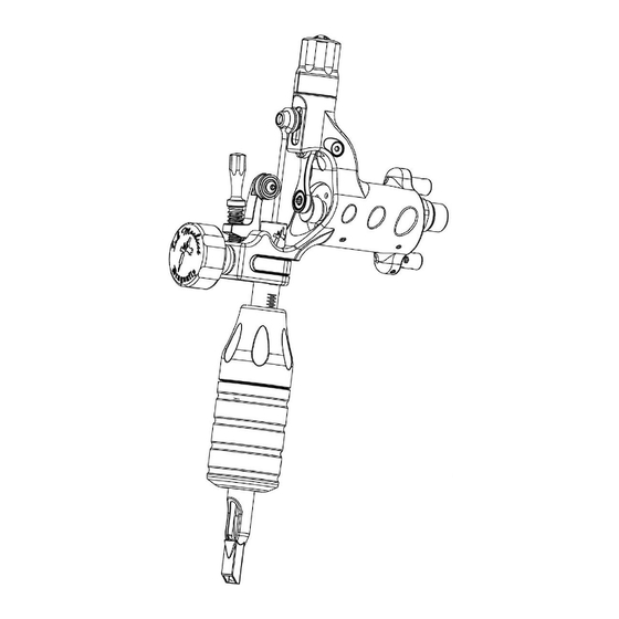
Specifications 0 - 13 volt DC (max. 13 volt DC) Input voltage Power connections RCA or clip cord (max. clip cord end diam Ø1,6 mm) Rpm range 0 - 8 000 rpm / min 0 - 130 / sec Stitches / sec 2.6, 3.7 and mm Adjustable Stroke length... - Page 31 Part names Note: Parts without numbers are not included in the purchase.
-
Page 33: Declaration Of Conformity
350 08 Växjö Sweden Equipment Tattoo machine Dragonfly X2 Year of manufacturer 2014 We InkMachines Sweden AB hereby declare that the Dragonfly tattoo machine specified above conforms with the following directives: Machine Directive 2006/42/EC Växjö 2010-05-07 …………………………………… Christian Johansson CEO...
Need help?
Do you have a question about the Dragonfly X2 and is the answer not in the manual?
Questions and answers