
Summary of Contents for Baudcom BD-OP-MUX32
- Page 1 Model: BD-OP-MUX32 32PCM+4GE+4E1+Console Voice Fiber Optical Multiplexer User’s Manual SHANGHAI BAUDCOM COMMUNICATION DEVICE CO.,LTD Website: http://www.baudcom.com.cn Email: info@baudcom.com.cn Tel: +86 21 37709251...
-
Page 2: Table Of Contents
32PCM voice multiplexer user manual 目录 1. OVERVIEW ................................2 2. FEATURES ................................2 3. PARAMETERS ..............................3 4. PANEL ..................................6 5. INDICATOR LED ..............................7 6. DIP SWITCH ................................. 8 7. FIBER PORTS ................................ 9 8. E1 PORTS ................................9 9. -
Page 3: Overview
1. Overview The 32channel POTs fiber multiplexer is a kind of developed point to point transmission equipment based on Baudcom PDH fiber transmission the special-use VLSI. This device provides 32Channel telephone 1-4Channel E1 interface, 4Channel 10/100/1000M Ethernet interface (Line Speed 1000M, Physical isolation) and 1 expansion interface. -
Page 4: Parameters
32PCM voice multiplexer user manual asynchronous data, such as RS232/RS485/RS422/Manchester code; 1-8Channel switch, two/four line audio and so on 1-30Channel voice access, supports caller ID feature and reverse polarity billing functions Support various sites mutual number allocation function ... - Page 5 32PCM voice multiplexer user manual Receiver sensitivity: -28dBm (Min) Link budget: 16dBm Single-mode Fiber 8/125um, 9/125um Maximum transmission distance: 40Km Transmission distance: 40KM@9/125um single mode fiber, attenuation (0.35dbm/km) Wave Length: 1310nm Transmitting power: -9dBm (Min) ~-8dBm (Max) Receiver sensitivity: -27dBm (Min) Link budget: 18dBm ...
- Page 6 32PCM voice multiplexer user manual Interface Standard: comply with protocol G.703; Interface Rate: 2048Kbps±50ppm; Interface Code: HDB3; E1 Impedance: 75Ω (unbalance), 120Ω (balance); Jitter tolerance: In accord with protocol G.742 and G.823 Allowed Attenuation: 0~6dBm Ethernet interface (10/100/1000M) Interface rate: 10/100/1000Mbps, half/full duplex auto-negotiation Interface Standard: Compatible with IEEE 802.3, IEEE 802.1Q (VLAN)
-
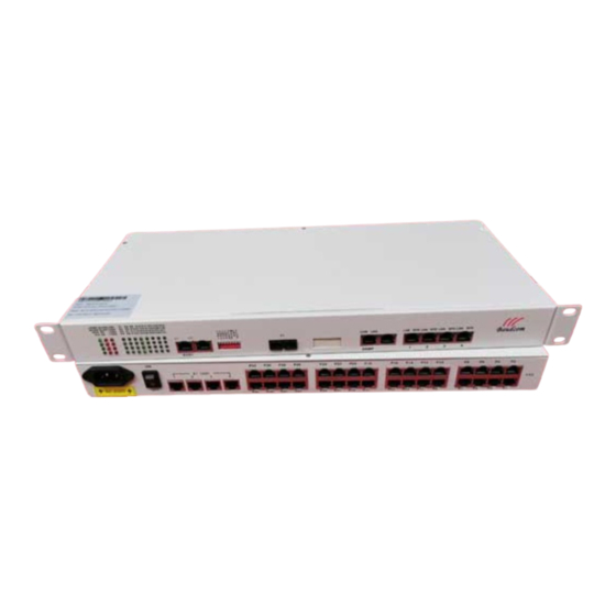
Page 7: Panel
32PCM voice multiplexer user manual 4. Panels Figure 1: front panel function distribution diagram Figure 2: function distribution diagram of 75 Euro E1 rear panel Figure 3: function distribution diagram of 120 Euro E1 rear panel... -
Page 8: Indicator Led
32PCM voice multiplexer user manual 5. INDICATOR LED NAME DESCRIPTION COLOR STATUS Device power is ON LPWR Green Device power is OFF The remote device power is ON RPWR Green The remote device power is OFF Fiber 1 connected Green Fiber 2 connected Green Correspoinding1~8 channel E1 signal loss... -
Page 9: Dip Switch
32PCM voice multiplexer user manual 6. DIP SWITCH DIP1 (1-4): COMMAND REMOTE E1 DIP1-1 DIP1-2 DIP1-3 DIP1-4 LOOP BACK All E1 not loop-back(Default) Remote NO.8 E1 Loop-Back Remote NO.7 E1 Loop-Back Remote NO.6 E1 Loop-Back Remote NO.5 E1 Loop-Back Remote NO.4 E1 Loop-Back Remote NO.3 E1 Loop-Back Remote NO.2 E1 Loop-Back Remote NO.1 E1 Loop-Back... -
Page 10: Fiber Ports
32PCM voice multiplexer user manual 7. Fiber ports Physical Interface: FC/SC (Optional), single-fiber and dual-fiber (Optional). Dual-Fiber: TX-Transmit RX-Receive Single-Fiber: Transmit and Receive (Note: 1310nm and 1550nm device used in pair) Note: the two fiber ports are used for 1+1 redundant. 8. - Page 11 32PCM voice multiplexer user manual 9. Telephone ports There are 32 RJ45 connectors on back panel, support 1-32 analog line telephones access. The device supports two interfaces: FXO and FXS. If this device is built-in FXO module, the interface is FXO interface, you can insert the phone line that that through switch into FXO interface.
-
Page 12: Ethernet Ports
32PCM voice multiplexer user manual 10. Ethernet ports 4Channel Physical isolation Ethernet can be optional. Support 10/100/1000M, half/full duplex auto- negotiation and AUTO-MDIX (crossed line and straightly connected line self-adaptable) Ethernet is connected Green Ethernet is not connected Blink 3 Times Ethernet rate is 1000M Green Blink 2 Times... - Page 13 32PCM voice multiplexer user manual A end Crystal head PIN B end crystal head PIN Twisted Pair Color PIN order PIN order Twisted Pair Color White and Orange White and Green Orange Green White and Green White and Orange Blue White and Brown White and Blue Brown...
- Page 14 32PCM voice multiplexer user manual Telnet provide graph interface mode( like the above one) and command line mode( enter from the “command mode” in the “others” menu under the graph interface mode.) User can set the IP address and other parameters of the device under the graph mode.
- Page 15 32PCM voice multiplexer user manual SNMP software This system provides a set of SNMP Management Software Snmp Manage to operate SNMP card and communication equipment. Please refer to the manual of SNMP software. MIB Information This system provides standard MIB variation. MIB Tree Definition In MIB tree, MIB variation behind 1.3.6.1.4.1.20353 is the one of communication equipment which is corresponding to this system.
- Page 16 32PCM voice multiplexer user manual SNMP card software upgrade The SNMP card software is stored in the FLASH. Software upgrade means FLASH programming by SNMP card software upgrade function. It needs software upgrade based on the 2 following situation. One is software upgraded, which means replace the old software in terminal server by new;...
- Page 17 32PCM voice multiplexer user manual Category: includes rack device (type: rack device) and others (type: SDH device, MSAP device, TDMoIP device and PCM Fiber MUX.) Since succeed to add rack, left Topology View management shows the homologous rack information. And can display/shield the position and quantity of business card in current running rack.
- Page 18 32PCM voice multiplexer user manual Check rack info.: select NM card, select NM card info. in right-click menu, and get following dialog. Check business card info.: double click business card or select “State Set” in right-click menu to enter the dialog. If the homologous .INF file is fixed, the state dialog should show out.
- Page 19 32PCM voice multiplexer user manual...
- Page 20 32PCM voice multiplexer user manual Console Interface Console sets interface. When matching 4 Ethernet interfaces, VLAN isolation mode can be set by Hyper Terminal. This is for PC hyper-terminal control. Use DB9 cable to connect the PC's COM port with CONSOLE port; Run the "hyper terminal"...
- Page 21 32PCM voice multiplexer user manual 1. current Ethernet information,Please input '1' [PDH /]:1 Local/Remote Ethernet Interface Link Status L1:Down ---- --- L2:Down ---- --- L3:Down ---- --- L4:Down ---- --- R1:Down ---- --- R2:Down ---- --- R3:Down ---- --- R4:Down ---- --- ==========Local VLAN======== separate mode is:special channel separate Information of separate set:Havn't Set Separated!
- Page 22 32PCM voice multiplexer user manual [PDH /]:3 local:1-30 Phone Type(S:FXS,O:FXO): 1 2 3 4 5 6 7 8 9 10 11 12 13 14 15 16 O O O O O O O O O O O O O O O O 17 18 19 20 21 22 23 24 25 26 27 28 29 30 31 32 O O O O O O O O O O O O O O O O Remote:1-30 Phone Type(S:FXS,O:FXO):...
- Page 23 32PCM voice multiplexer user manual == Exit, Please input '0' ====================================================================== [PDH /Bandwidth config]: “setl” for setting local equipment,and “setr” for setting remote side. x,y,z respectively denote hundred's place, decade and unit for a hundred number; a,b denote decade and unit for a ten number; m means port number, when m=0 denote optical connector, m=1/2/3/4 denote the 1st/2nd/3rd/4th ethernet port.
- Page 24 32PCM voice multiplexer user manual “setl” for setting local equipment,and “setr” for setting remote side. Mark: x means 1-4ch etherent port. 4.4 802.1P setting,input"4" [PDH /Config]:4 ==================== 802.1P Config ====================== == Enable local 802.1P : enl x,x=0:disable,x=1:enable=== == Enable Remote 802.1P : enr x,x=0:disable,x=1:enable=== == Local 802.1P user-priority command: setl x y == Remote 802.1P user-priority command: setr x y == Note:x:port number(x=1-4) y:value(y=0-7)
- Page 25 32PCM voice multiplexer user manual priority grade. Attention: when ethernet packet is with tag, the device will dedicate priority grade automaticly by tag; otherwise, use setting x y to set priority grade by real situation. 4.5 802.1Q switch setting, input "5" [PDH /Config]:5 ====================== 802.1Q Config ================================= == Note:You can choice one of 3,4,5,and 3,4 used for back-to-back ===...
- Page 26 32PCM voice multiplexer user manual == Set Local Channel Separate : setl x == Set Remote Channel Separate : setr x == Note: x:Channel Separate mode ( x=0-4 ) == Explanation of Channel Separate mode : == Mode 0( x=0 ) : Disable Channel Separate == Mode 1( x=1 ) : Special Channel Separated,and untagged == Mode 2( x=2 ) : Special Channel Separated,and tagged == Mode 3( x=3 ) : 802.1Q Channel Separated,and untagged...
- Page 27 32PCM voice multiplexer user manual Channel isolation instruction: each channel isolates to each other; 4.7 Ethernet packet switch between 1536 and 1916, input "7 [PDH /Config]:7 Accept packet sizes form 1916 bytes to 1536 bytes! The device has two types of packet:1916 and 1538, each ethernt port should be setted unified.
- Page 28 32PCM voice multiplexer user manual y=4:1 hours;y=5 5 hours;y=6:24 hours;y=7 Forever === ==Note:x=11,Equipment reset, ==Note:x=12,Equipment Re-Boot, ==Note:x=13,Restore to factory settings =========================================================== [PDH /PDH Config]: “setl” for setting local equipment,and “setr” for setting remote side. Mark: x means 1-12 command word, Command x describe Let the Local E1 Loop-back...
- Page 29 32PCM voice multiplexer user manual == 5.中英文切换,请输入'5' == 6.恢复出厂设置,请输入'6' =========================================== [Future /]:...
-
Page 30: Aux Ports(Optional
32PCM voice multiplexer user manual 12. AUX interface(optional) Can extend all kinds of data (according to your order) The RJ45 interface of L1-L4 on the back panel is 1-4Channel Data. PIN1-4 is 1Channel, PIN5-8 is 2Channel. Defined as follows:... -
Page 31: Power
32PCM voice multiplexer user manual 13. POWER Device supports AC100V-260V, DC -48V (Optional) If you use AC100V-260V power, you should connect device power input port with power socket by using random power line to provide AC100V-260V power device. If you use DC to supply power, DC-48V as an example, please connect as follows: “FG”... -
Page 32: After Sales
4. Our products don’t match with other company products because of bad design to cause damage. 15. COMPANY STATMENT 1. As we are adopting new technology, if our product technical parameters are changed, we won’t notice you. 2. The final interpretation right of this manual belongs to Baudcom.
Need help?
Do you have a question about the BD-OP-MUX32 and is the answer not in the manual?
Questions and answers