Landmark L3015UI1 Series Service Manual
Hide thumbs
Also See for L3015UI1 Series:
- Owner's manual (16 pages) ,
- Owner's manual (32 pages) ,
- Owner's manual (16 pages)
Table of Contents
Advertisement
Quick Links
Advertisement
Table of Contents

Related Manuals for Landmark L3015UI1 Series


Summary of Contents for Landmark L3015UI1 Series
- Page 1 Landmark Service Manual Wine Cooler Landmark L3015UI1XXX Series Landmark L3024UI1XXX Series Landmark L3024UI2XXX Series CAUTION: READ ALL SAFETY PRECAUTIONS IN THIS MANUAL BEFORE SERVICING THE UNIT *Warranty service should be performed by an authorized service representative only...
-
Page 2: Safety Precautions
SAFETY PRECAUTIONS WARNING: This manual and the information contained herein is intended for use by certified technicians. The manu- facturer or seller is not responsible for the interpretation or misuse of the information provided, nor does it assume any liability in connection with its use. The safeguards and warnings indicated in this manual do not cover all possible conditions which may occur. - Page 3 Electrical Safety • Do not exceed the power outlet ratings. • It is recommended that the unit be connected to its own circuit. • A standard electrical supply that is properly grounded in accordance with the National Electrical Codeand all state and local codes and ordinances is required.
-
Page 4: Table Of Contents
Contents Safety Precautions Parts Identification Disassembly Shelves Light Display Board Control Board Sensor(S) And Fan Door Switch Compressor/Ptc Starter/Overload Protector Troubleshooting Compressor Components Electrical Components Service Diagnostic Chart Refrigerating Cycle PCB Board PCB Description ADDITIONAL SAFETY PRECAUTIONS Please read the followings before servicing your appliance. 1. -
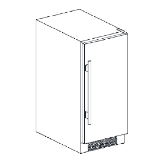
Page 5: Parts Identification
PARTS IDENTIFICATION Models: L3015UI1WSG-LH / L3015UI1WSG-RH Top Right Hinge Carbon Filter Shelf SS Door Frame Door Handle Control Panel Lower Right Hinge Door Lock Leveling Legs Door Switch Models: L3015UI1WSG-LH / L3015UI1WSG-RH Top Right Hinge Shelf Carbon Filter SS Door Frame Door Handle Control Panel... - Page 6 PARTS IDENTIFICATION Models: L3024UI1MSG-LH / L3024UI1MSG-RH Top Right Hinge Carbon Filter Shelf SS Door Frame Door Handle Control Panel Lower Right Hinge Door Lock Leveling Legs Door Switch Models: L3024UI1BSG-LH / L3024UI1BSG-RH Top Right Hinge Shelf Carbon Filter SS Door Frame Door Handle Control Panel...
- Page 7 PARTS IDENTIFICATION Models: L3024UI1WSG-LH / L3024UI1WSG-RH Top Right Hinge Carbon Filter Shelf SS Door Frame Door Handle Control Panel Lower Right Hinge Door Lock Leveling Legs Door Switch Models: L3024UI2WSG-LH / L3024UI2WSG-RH Top Right Hinge Carbon Filter Shelf Control Panel Carbon Filter SS Door Door Handle...
-
Page 8: Disassembly
DISASSEMBLY Shelves Removing the shelves 1. Open the door completely. The door must be able to open at least 90 degrees for the shelves to properly MODELS: clear the door gasket. L3015UI1WSG-LH / L3015UI1WSG-RH 2. Holding both the left and right sides of the shelf you L3015UI1BSG-LH / L3015UI1BSG-RH intend to remove, lift the front up out of the key slot on the front vertical tracks. -
Page 9: Light
DISASSEMBLY Light 3. Check the wired connection for a loose connection. MODELS: L3015UI1WSG-LH / L3015UI1WSG-RH L3015UI1BSG-LH / L3015UI1BSG-RH L3024UI1MSG-LH / L3024UI1MSG-RH L3024UI1BSG-LH / L3024UI1BSG-RH L3024UI1WSG-LH / L3024UI1WSG-RH L3024UI2WSG-LH / L3024UI2WSG-RH Checking and changing the light 1. Use a flathead screwdriver or other tool to pry the bottom light cover off of the unit. -
Page 10: Display Board
DISASSEMBLY Display Board 6. Remove the faulty display board. MODELS: L3015UI1WSG-LH / L3015UI1WSG-RH L3015UI1BSG-LH / L3015UI1BSG-RH L3024UI1MSG-LH / L3024UI1MSG-RH 7. Install a new supply board. L3024UI1BSG-LH / L3024UI1BSG-RH 8. Reinstall the two display board screws. 9. Connect the new display board to the wired connector. L3024UI1WSG-LH / L3024UI1WSG-RH 10. - Page 11 DISASSEMBLY Display Board 4. If the wired connection is not loose, change the display board. MODELS: 5. Unplug the faulty board from the wired connector. L3024UI2WSG-LH / L3024UI2WSG-RH 6. Remove the board from the bracket. Checking and changing the display board 1.
-
Page 12: Control Board
DISASSEMBLY Control Board 4. Unscrew the three (3) screws from the control board bracket. MODELS: L3015UI1WSG-LH / L3015UI1WSG-RH L3015UI1BSG-LH / L3015UI1BSG-RH Checking and changing the control board 1. Remove the four screws from the back cover. 5. Check the wired connectors for a loose connection. 2. - Page 13 DISASSEMBLY 8. Remove the screws from the faulty control board. 9. Depress the standoffs by squeezing them with a needle nose pliers. 10. Remove the old control board. 11. Install a new control board. 12. Reinstall the screws in the new control board. 13.
- Page 14 DISASSEMBLY Control Board 5. To change the control board, first disconnect all wired connections. MODELS: NOTE: For the power cord connector, use a needle inserted in the round hole to remove. L3024UI1MSG-LH / L3024UI1MSG-RH L3024UI1BSG-LH / L3024UI1BSG-RH L3024UI1WSG-LH / L3024UI1WSG-RH Checking and changing the control board 1.
- Page 15 DISASSEMBLY Control Board NOTE: For the power cord connector, use a needle inserted in the round hole to remove. MODELS: L3024UI2WSG-LH / L3024UI2WSG-RH Checking and changing the control board 1. Remove the four screws from the back cover. 6. Remove the screws from the faulty controlboard. 2.
-
Page 16: Sensor(S) And Fan
DISASSEMBLY Sensor(s) and Fan 4. Unscrew the six screws from the air duct boar MODELS: L3015UI1WSG-LH / L3015UI1WSG-RH L3015UI1BSG-LH / L3015UI1BSG-RH Checking and changing the sensor(s) and/or fan 1. Take out all the shelves. 2. Unscrew the three screws from the air duct board. 5. - Page 17 DISASSEMBLY 6. If no connections are lose, replace the fan or the 11. To replace a sensor, remove the EVA and tinfoil. sensor(s). 12. Remove the sensor bracket. Sensor Defrost Sensor 13. Reverse the air duct board and remove the bracket. 14.
- Page 18 DISASSEMBLY Sensor(s) and Fan 4. Unscrew six screws from the air duct board. MODELS: L3024UI1BSG-LH / L3024UI1BSG-RH L3024UI1WSG-LH / L3024UI1WSG-RH L3024UI1MSG-LH / L3024UI1MSG-RH Checking and changing the sensor(s) and/or fan 1. Take out all the shelves. 2. Unscrew the three screws from the air duct board. 5.
- Page 19 DISASSEMBLY 6. If no connections are lose, replace the fan or the 11. To replace a sensor, remove the EVA and tinfoil. sensor(s). 12. Remove the sensor bracket. Sensor Defrost Sensor 13. Reverse the air duct board and remove the bracket. 14.
- Page 20 DISASSEMBLY Sensor(s) and Fan 5. Unscrew the seven screws from the upper air duct board cover. MODELS: 6. Take out the upper air duct cover. L3024UI2WSG-LH / L3024UI2WSG-RH Checking and changing the sensor(s) and/or fan 1. Remove the two screws from the middle display board. 7.
- Page 21 DISASSEMBLY 10. Unscrew the six screws from the air duct board. Upper sensor and 11. Take out the air duct board. fan connector Lower sensor and fan connector 14. If no wired connections are loose, replace the fan(s) and/or sensor(s). 15.
- Page 22 DISASSEMBLY 16. Unscrew the four screws around the fan. 17. Remove the faulty fan. 18. Install a new fan. 19. Replace the four screws. 20. To replace a sensor, remove the EVA and tinfoil. 21. Remove the sensor bracket. 22. Reverse the air duct board and remove the bracket.
-
Page 23: Door Switch
DISASSEMBLY Door Switch 3. Remove the four screws on the support bar. MODELS: L3015UI1WSG-LH / L3015UI1WSG-RH L3015UI1BSG-LH / L3015UI1BSG-RH L3024UI1MSG-LH / L3024UI1MSG-RH L3024UI1BSG-LH / L3024UI1BSG-RH L3024UI1WSG-LH / L3024UI1WSG-RH L3024UI2WSG-LH / L3024UI2WSG-RH 4. Remove the support bar. Checking and changing the door switch 1. - Page 24 DISASSEMBLY 8. Remove the screw bracket 11. Install a new door switch. 9. Unplug the connector. 12. Reassemble, using the steps in reverse.. 10. Press the hook on door switch and remove it.
- Page 25 DISASSEMBLY Compressor/Starter Relay/ 3. Check the relay and overload connectors. Overload Protector MODELS: L3015UI1WSG-LH / L3015UI1WSG-RH L3015UI1BSG-LH / L3015UI1BSG-RH L3024UI1MSG-LH / L3024UI1MSG-RH L3024UI1BSG-LH / L3024UI1BSG-RH L3024UI1WSG-LH / L3024UI1WSG-RH L3024UI2WSG-LH / L3024UI2WSG-RH 4. If the connectors are secure, replace the relay and/or Checking and changing the compressor- overload protector.
-
Page 26: Compressor/Ptc Starter/Overload Protector
TROUBLESHOOTING Compressor Components Check the resistance Check the among M-C, S-C, and M-S resistance of Replace the in the motor compressor. the motor compressor. Is it normal? compressor. Check the Check the resistance of resistance of the two terminals in the Replace the the PTC starter. -
Page 27: Electrical Components
TROUBLESHOOTING Electrical Components Cooling is impossible Compressor Check if current flows to does not run. Cause the following components. Starting devices Shorted or broken. Poor contact or shorting. Compressor coil Coil shorted. Replace each Cicuit parts Poor contact or shorting. component. -
Page 28: Service Diagnostic Chart
TROUBLESHOOTING SERVICE DIAGNOSTIC CHART Problem Possible Cause Appliance does not operate. Not plugged in. The appliance is turned off. The circuit breaker tripped or a blown fuse. Appliance is not cold enough. Check the temperature control setting. External environment may require a higher setting. - Page 29 TROUBLESHOOTING Single zone The air sensor is open circuit failed. Connection main control Single zone PCB is with white color wires. Check the circuit, if it is normal, Display error code “E1”( ) the sensor need to be replaced. The air sensor is short circuit failed. Connection main control Single zone Display error code “E2”(...
-
Page 30: Refrigerating Cycle
TROUBLESHOOTING REFRIGERATING CYCLE TEMPERATURE STATE OF STATE OF THE CAUSE REMARKS OF THE THE SET EVAPORATOR COMPRESSOR PARTIAL Appliance Low flowing sound of A little high • A little Refrigerant LEAKAGE Refrigerant is heard and more than discharges. don't get cold frost forms in inlet only ambient •... -
Page 31: Pcb Board
PCB BOARD PCB DESCRIPTION MODELS: L3015UI1WSG-LH / L3015UI1WSG-RH L3015UI1BSG-LH / L3015UI1BSG-RH L3024UI1MSG-LH / L3024UI1MSG-RH L3024UI1BSG-LH / L3024UI1BSG-RH... - Page 32 PCB BOARD PCB DESCRIPTION MODELS: L3024UI2WSG-LH / L3024UI2WSG-RH...
- Page 33 DATE REVISION NOTES 10/26/2022 Initial Release...