Table of Contents
Advertisement
Quick Links
Advertisement
Table of Contents

Subscribe to Our Youtube Channel
Summary of Contents for Meditech 12.1 inch portable
- Page 2 The model of the parameters slightly different configuration of the functional configuration parameters, detailed see "model function" and chapters table the detailed description of! Apply the product model in the list below 12.1 inch portable 12.l inch slim type 7 inch portable 15 inch slim type...
-
Page 3: Table Of Contents
User’s Manual of Patient Monitor Contents Safety Instruction................... 4 Chapter 1 Introduction ................5 Chapter 2 Installation ................13 Chapter 3 Systmes Menu ..............16 Chapter 4 Alarm Function ..............26 Chapter 5 Recorder ................39 Chapter 6 Review…………………………………..………………….38 Chapter 7 System interface ..............45 Chapter 8 ECG / RESP Monitor ............ -
Page 4: Safety Instruction
User’s Manual of Patient Monitor Safety Instruction Any operator must read the following text carefully before using the monitor. This text will tell operator the operation steps. Incorrect operation may cause malfunction and danger that may harm the monitors or persons. Any malfunction or harm to the persons or monitors is caused by wrong operation that can be avoided absolutely if according to the instruction indicated in this text, manufacturer would be not responsible for the safety, reliability and performance assurance. -
Page 5: Chapter 1 Introduction
User’s Manual of Patient Monitor Chapter 1 Introduction Applicable scope This series patient monitor be bsed to Detection of patients ECG/ HR、TEMP、 RESP、NIBP、SPO2、EtCO2 and IBP. Different types of products related functional description: Functio ECG/HR TEMP(T1/T2) RESP NIBP/PR SpO2/PR EtCO IBP(I1/I2) Model 12.1 inch □... - Page 6 User’s Manual of Patient Monitor...
- Page 7 User’s Manual of Patient Monitor ◆ Because of the different product model and some module is optional configuration, so you purchase the monitor may be not have certain functions or the corresponding interface, please see the models of the corresponding description.
- Page 8 User’s Manual of Patient Monitor USB socket Signal output waveform instructions area display (51) tip information area (52) ( 53) interface Antenna interface (54) 1.3 Control view ◆ The product has many cabinet symbols, this symbol tips please be careful operation, which see random material and product specifications in the description and requirements.
- Page 9 User’s Manual of Patient Monitor ● 39—— remote control knob received through the window:Infrared remote control for receiving a instructions. ● 41—— battery status indicator:Used for the state of the storage battery charging and discharging real-time instructions. ● 42——remote control receiving indicator light: Press the remote and accept to remote control signal instructions.
- Page 10 User’s Manual of Patient Monitor without any display, it means this parameter is under alarm sound indication function. ◆ When the mark occurs, systems won’t carry out the alarm sound function. Therefore, users should use this function carefully. 50----Waveforms Area It mainly shows waveforms of parameters, the left corner is the name of waveforms.
- Page 11 User’s Manual of Patient Monitor 1.5 Lithium battery Configuration: various models of monitor of the corresponding lithium ion battery model see the table below: Battery Battery Standby Model Appearance Specifications model appearance time Li-ion Battery 12.1” ≥2 hours TB0802 11.1V / portable 4400mAh Li-ion Battery...
- Page 12 User’s Manual of Patient Monitor 12”Slim type Steps described 1. Cut down power supply, pull out of power supply line. 2. Reverse place host, remove the four host screws; 3. Flip host and open, carefully excision and pulled out relevant connectors;...
- Page 13 User’s Manual of Patient Monitor 1.6 Remote controller specification: 1. Left key 2. Right key 3.Confirm key 4. Start key 5. Menu key 6.Silent key 7. Freezing key 8.Print key(optional) 9. Optional key (Not available now) 10. Infrared emitter 11.Battery position 12.
-
Page 14: Chapter 2 Installation
User’s Manual of Patient Monitor Chapter 2 Installation ◆ Open the packing carton and check the accessories. ◆ Connect the grounding end of the monitor. ◆ Check input power supply and earthing. ◆ Connect the sensor, cuff to the patient. ◆... - Page 15 User’s Manual of Patient Monitor ① Standard configuration (without storage battery): check AC power supply cable. Turn on the main switch of power supply on the rear side of the monitor, then the indicatior light will be on, enter into the main screen of monitor after self-inspection of the system,then user can operate it normally.
- Page 16 User’s Manual of Patient Monitor AC power supply or battery No display power green Always on AC input instructions Battery-powered or AC not AC indicator No display connected ◆ Press the soft switch gently again for one second to swith off the system. If the patient monitor is in the standby state for a long time, the user should turn off the main switch of power supply and take the storage battery out of the monitor.
-
Page 17: Chapter 3 Systmes Menu
User’s Manual of Patient Monitor Chapter 3 Systmes Menu It introduces “Systems menu”, others will be clarified in following chapter 3.1 Patient information manage 3.2 Default 3.3 Recall 3.4 Monitor information 3.5 Monitor setup 3.6 Monitor maintenance 3.7 Drug calculation 3.8 Demo This monitor is configurated flexibly. - Page 18 User’s Manual of Patient Monitor ◆ Sex: Male or Female ◆ Patient type: Adult, pediatric, neonate ◆ Pace: on or off ◆ New patient : receive new patient ,but not delect the previous data In this menu, users can choose“new patient”to enter “Confirm to update patient”,as pic.3-3 3-3 Confirm to update patient Select“Yes”,delete all data of currently monitored patient and exit the menu Select“No”,continue to store the data, and exit the menu...
- Page 19 User’s Manual of Patient Monitor There are “NIBP recall”,“Alarm recall”,“Trend Graph”,“Trend table”and so on, for more details,please refer to Recall function. 3.4 Monitor Information Select “Monitor information”in “System menu” to check the version information of monitor, like pic.3-6 for reference, the actual content is accord to each monitor. 3-6 Monitor Versions Select “Device Config list”to check the configuration of monitor, refer to pic.3-7 3-7 Device config list...
- Page 20 User’s Manual of Patient Monitor 3-8 Monitor setup The submenu available in this menu: ◆ Face select: take reference to System menu ◆ The alarm limit: open is the parameters that in next to the parameters that the alarm limit; Close is the parameters in next to the parameter not display the alarm limit ◆...
- Page 21 User’s Manual of Patient Monitor 3-10 Record set up In this menu, users can set up the following items: ◆ Waveforms 1 Select the first waveforms for output, but keep different choice with Waveforms 2, otherwise system will adjust automatically ◆...
- Page 22 User’s Manual of Patient Monitor 3.6 Monitor maintenance Select “Maintain”in “System menu”,pop up“maintenance password”window, pic.3-12 3-12 Maintenance password In this menu, users can enter user password to maintain monitor.Users can’t carry out factory maintenance function, it is only for factory. Rotate the knob, enter user’s password: , and press “confirm”,appearing user maintain as 2016...
- Page 23 User’s Manual of Patient Monitor ◆ Incorrect settings may cause the damage to the battery and inaccurate information. ◆Alarm pause time:Pause time can be modified in “1” “2” “3”minutes ◆ Color self-define: Define the color shown on waveforms and parameters 3-14 Color self-define In this menu, users can setup the color shown on each parameter’s waveforms and parameter on the screen as requirements.
- Page 24 User’s Manual of Patient Monitor 3-15 System Events ◆ Up-down In this menu, it will show 10sets of information at the most. If more,users can choose “up-down” to browse more information ◆ Record This key is not available for status inforamtion. 3.7 Drug calculation Select “Drug calculation”...
- Page 25 User’s Manual of Patient Monitor appropriate unit according to Doctor’s requirement.In the same unit’s series, the scale of unit will be adjusted automatically with the parameter’s values.When some parameter’s values exceed the scope of unit, it will display “--”.Users can define the drug’s unit as follows: ◆...
- Page 26 User’s Manual of Patient Monitor ◆ Titration is a separated function from monitor.The subject can be patient not monitored. It won’t have effect on patient when making operation on Titration window 3.8 Demo Select “Demo” in system menu, display entering password window. Enter the correct password , “5188”...
-
Page 27: Chapter 4 Alarm Function
User’s Manual of Patient Monitor Chapter 4 Alarm Function ◼ This chapter introduces the general information and measures will be taken ◼ Refer to each parameter’s alarm and indicating information in each parameter’s setting ◆12 " slim type Monitor products do not have separate warning lights. 4.1 General Alarm is an indication to users when patient monitored have changes of vital sign or when monitor itself has malfunction... - Page 28 User’s Manual of Patient Monitor RESP heart disturbance; RESP apnea; The other belonged to the former case. 4. 2. 1. 2 Alarm level Every alarm, whether technical or physical alarm, both have a level of features, the higher the level, when this alarm occurs, the system will be more people in a way suggesting that the alarm alert.
- Page 29 User’s Manual of Patient Monitor 4. 3. 2 Words characteristics Background: High alarm background color is red, intermediate and low-level warning alarm background color is yellow. String color: In addition to alarm NIBP technology area, regardless of the alarm level, has been black.
- Page 30 User’s Manual of Patient Monitor 4. 4. 4 Alarm suspended status When the alarm suspension of the following treatments: Ban all alarm sound and light tips." Ban all physical alarm text prompts. The physical alarm description area the number of seconds left suspended. Able to clear the sound and light alarm, the alarm to prompt information Able to remove the alarm, clear the alarm information 4.
- Page 31 User’s Manual of Patient Monitor the alarm is not in the state), the alarm will occur silently related to the following changes: 1、Measurement parameters and alarm limits are no longer related to flash. 2、 describes the prompt entry in the alarm after a previous state of the system time into the trigger.
- Page 32 User’s Manual of Patient Monitor Settings” menu, you can set the alarm on the HR set. The user can set the five elements, namely the "heart rate alarm", "alarm level", "alarm records", "Alarm high limit", "low alarm limit”. Users can rotate the button to move the cursor to set the options, press the spin button to be set.
- Page 33 User’s Manual of Patient Monitor 4.6.3 When the power to lead off When the power, if you open the parameter module is not connected leads, then the following treatment: 1、About ECG or SPO2 Module will lead to tips off alarm (automatically clear sound and light), and then prompts the user.
- Page 34 User’s Manual of Patient Monitor...
- Page 35 User’s Manual of Patient Monitor SPO2 alarm upper limit SPO2 SPO2 alarm low limit PR alarm upper limit PR alarm low limit alarm upper limit RESP Alarm low limit T1 alarm upper limit 39.0 39.0 39.0 T1 alarm low limit 36.0 36.0 36.0...
- Page 36 User’s Manual of Patient Monitor 4.8.1.3 In this menu, users can choose “system menu” to enter “default”,as picture follows Specific operation: into the corresponding parameter Settings, then select the "default configuration", enter the choice "yes", and then to the current a preset parameters of the alarm on restoration.
- Page 37 User’s Manual of Patient Monitor RR too low Physiological alarm Can set RESP breathing suffocation Physiological alarm High SpO2 SPO2 too high Physiological alarm Can set SPO2 too low Physiological alarm Can set PR too high Physiological alarm Can set PR too low Physiological alarm Can set...
- Page 38 User’s Manual of Patient Monitor Over-voltage protection Technology alarm High NIBP system failure Technology alarm High Measurement overtime Technology alarm High Manual measuring Prompt Word Automatic measurement Prompt Word Consecutive measurements Prompt Word Measurement termination Prompt Word Calibration... Prompt Word Calibration termination Prompt Word...
- Page 39 User’s Manual of Patient Monitor to identify the cause of the alarm and in accordance with the alarm to take corresponding measures. 1) Check the patient's condition. 2) Identify which parameters are alarm or what kind of alarm is occurring. 3) To identify the reasons for alarm.
-
Page 40: Chapter 5 Recorder
User’s Manual of Patient Monitor Chapter 5 Recorder ■ This chapter describes the functions related to the contents of the printed output. ◆ Recorder Overview ◆ Recording method ◆ Record information ◆ 12 "Wall slim type Monitor product do not support recording and printing functions. - Page 41 User’s Manual of Patient Monitor ◆ When the output operation is running, press the Print key parameters of the output will wait until after the end of the output current output. 5.3 Record Output Data and time HR-- Heart rate PR--Pulse rate SPO2—SPO2 SYST-- Systolic blood pressure...
- Page 42 User’s Manual of Patient Monitor prompting signal. For example: out of paper, communication errors. External recorder connected operation The TR-J03 external recorder for the TR-900E 15-inch series, connection steps as follow: ◆ turn off the power of the monitor; ◆ Connect and fix external recorder and the host plate by M3 * 10 combination screw; ◆...
-
Page 43: Chapter 6 Review
User’s Manual of Patient Monitor Chapter 6 Review In the “System Menu” select “review function”, Review of the following functions: 6.1 NIBP measurement review 6.2 Review of alarm events 6.3 Review of trends 6.4 Review of trends in Table .1 NIBP measurement review It can review the recent review of 400 sets of NIBP measurement data. - Page 44 User’s Manual of Patient Monitor 6-2 Alarm Conditions Review In this menu, users can set the alarm review conditions, contains the following items:" ◆ Review timing of alarm Set the review of the "start time" and "end time." ◆ Review timing of alarm In the "Select the alarm incident review", according to the review of the parameters need to select "All", "ECG", "SPO2", "NIBP", "RESP", "TEMP", "HR-H>180"...
- Page 45 User’s Manual of Patient Monitor 6-3 Review of alarm events Front page: monitor can store up to 70 alarm events, but "Alarm Event Review" window can only display a warning event. Select the "Front page " key, then turn the knob, can be observed earlier or later the alarm event;"...
- Page 46 User’s Manual of Patient Monitor As shown above, trend graph shows the “Preferences” in the selected parameter trend curve. If you select “NIBP” that not displayed on the trend curve, and the “S” on behalf of systolic blood pressure to “D” on behalf of diastolic blood pressure with “M” represent the average pressure. Vertical axis measured value, the abscissa is the measured time.
- Page 47 User’s Manual of Patient Monitor example, some trend data is bigger than the biggest value of vertical coordinate, the “amplitude modulation” item should be adjusted; ◆ Select “wavering cursor” and remove the cursor to some time. And the time will be displayed above the graph while the measurement value will be displayed below the graph;...
- Page 48 User’s Manual of Patient Monitor Watch much later or earlier trend graph: indicator in the top of the window, select “turn to next or above page”, and then If there is rotate the shuttle in clockwise in order to look at the later trend graph. If there is indicator in the bottom of the window, select “turn to next or above page”, and then rotate the shuttle in anti-clockwise in order to look at the later trend graph.
-
Page 49: Chapter 7 System Interface
User’s Manual of Patient Monitor Chapter 7 System interface ■ chapter describes the introduction of this series monitor the contents of the main display screen. Monitor you purchased version of the system interface may be different pictures in this section. Picture for reference only, please show the actual content of the product shall prevail. - Page 50 User’s Manual of Patient Monitor 7-2 Standard interface 7.2 The trend of co-existence interface In the "working interface options" menu, select "trend coexistence interface", then press the knob, then enter into the coexistence of the interface shown below: 7-3 Trend of coexistence interface ◆...
- Page 51 User’s Manual of Patient Monitor ◆ Trends Length: the length of dynamic short trends is 2 hours, as shown above, the bottom of the trend graph below shows the time scale, the right side is 0 hours, the left is -2 hours. ◆...
- Page 52 User’s Manual of Patient Monitor 7-5 Big font interface As shown above, in Big font interface, ECG, SPO2 and diastolic blood pressure / mean pressure / systolic blood pressure (NIBP) are using a Big font, on the left shows ECG, SPO2 and RESP waveform.
-
Page 53: Chapter 8 Ecg / Resp Monitor
User’s Manual of Patient Monitor Chapter 8 ECG / RESP Monitor 8.1 Overview ECG defined patients with electrocardiographic monitoring cardiac electrical activity produces a continuous waveform in order to accurately assess the physiological state of the patient at that time. ECG cable connection should be correct, so as to obtain the correct measurements. The portable monitor in normal operation status shows two ECG waveforms. - Page 54 User’s Manual of Patient Monitor ◆ electrode polarization: overload monitor should be able to quickly recover. However, in the defibrillation process, the current flows through the electrodes at the skin contact, resulting in polarization. Some different materials of the electrodes may become highly polarized, full recovery would be a very difficult task.
- Page 55 User’s Manual of Patient Monitor To U.S. standards, for example, five-lead electrode placement shown in Figure 8-1: ◆ RA White (right arm) electrode –place under the clavicle, near the right shoulder. ◆ LA Black (left arm) electrode --place under the clavicle, near the left shoulder. According to below photo to place on the chest.
- Page 56 User’s Manual of Patient Monitor Europe standard uses R, L, N, F, C, to show the leads, while the U.S. standard uses RA, LA, RL, LL, V to show). United States (AHA) European (IEC) lead name Lead color lead name Lead color White Black...
- Page 57 User’s Manual of Patient Monitor 3 - Filtering mode more accurate waveform can be obtained by filtering, filtering methods are the following three options: ◆ Diagnosis: display the ECG waveform without filtering; ◆ monotoring: filter the pseudo-difference that may lead to false alarms; ◆...
- Page 58 User’s Manual of Patient Monitor ◆ When using with electrosurgery (ES) equipment (high-frequency surgical equipment) simultaneously, do not place the electrodes near the grounding plate of surgical equipment, or ECG signal will be a lot of interference. Don’t put ECG electrodes between the grounding plate of the ES and the electric surgical knife on the middle to avoid burns.
- Page 59 User’s Manual of Patient Monitor 8-6 ECG setup menu In this menu, the user can set the following items. Your monitor may not have some of the items. ◆ Heart rate alarm: On: when heart rate alarm occurs, to prompt and store the alarm . Off: when heart rate alarm occurs, not to prompt and store the alarm.
- Page 60 User’s Manual of Patient Monitor ◆ Calculating channel "Channel 1" represents the first wave of the ECG waveform data is taken to calculate heart rate. "Channel 2" represents the second wave of the ECG waveform data is taken to calculate heart rate. "Auto”: automatic selection for the calculation of heart rate monitor channel.
- Page 61 User’s Manual of Patient Monitor ◆ In the configuration of the monitor from the manufacturers, ST segment analysis function is...
- Page 62 User’s Manual of Patient Monitor turned off; ◆ When openning the ST segment analysis, the monitor will automatically switch to the "diagnosis" mode; ◆ Users may select the "Monitoring" or "Operation" mode, but ST segment data will be seriously distorted; ◆...
- Page 63 User’s Manual of Patient Monitor 8-9 confirm ST segment analysis points In this window, select "ISO" or "ST" button, you can adjust the position of ISO and ST point.
- Page 64 User’s Manual of Patient Monitor ISO: base point, is used to set baseline points of ST segment analysis; ST: starting point, is used to set the measurement points of ST segment analysis. 8.5.2 Arrhythmia analysis In the "ECG Settings" menu, select "arrhythmia analysis" to enter the menu shown in Figure 8-10: In this menu, the user can set the following items: 8-10 arrhythmias ◆...
- Page 65 User’s Manual of Patient Monitor In the "arrhythmia analysis" menu, select "ARR alarm settings" to enter the menu shown in Figure 8-11:...
- Page 66 User’s Manual of Patient Monitor 8-11 arrhythmia alarm settings In this menu, the user can set the following items: ◆ Select arrhythmia, total 13 options: MISSED BEATS, ASYSTOLE, VFIB / VTAC, R ON T, UT> 2, COUPLET, PVC, BIGEMINY, TRIGEMINY, TACHY, BRADY, PNC, PNP; Among which ALM is the alarm switch, REC is the alarm record switch, LEV is the alarm level;...
- Page 67 User’s Manual of Patient Monitor 8-13 full-screen display multi-lead ◆ Heart beat sound volume :can choose the volume level 0,1,2,3,4. ◆ Pacing Analysis On: when pacing signal is detected, to label symbol "¹" above the ECG waveform; Off: Turn off the pacing analysis function; ◆ST-segment measurements of the two alarm is the same, not separate alarm limits set for each channel.
- Page 68 User’s Manual of Patient Monitor ◆ alarm information Alarms may occur in ECG measuring are divided into two kinds: physiological alarm and...
- Page 69 User’s Manual of Patient Monitor technological alarm, at the same time it may also produce a variety of tips. When these alarms or prompts appear, the monitor is characterized by visual and auditory representation that user can refer to the relevant section of the alarm function described. On the screen, physiological alarms and general tips (general alarm) are displayed in alarm zone, and, the technological alarm and the messages which can not be triggered are displayed in the information zone.
- Page 70 User’s Manual of Patient Monitor ECG module Accidentally high If the failure going on, the communication error communication treatment is the same as above. failure HR alarm limit error Functional safety high Stop using HR alarm function, and failures notice biomedical engineer or maintenance person of the Company.
- Page 71 User’s Manual of Patient Monitor Electrode placement for the measurement of respiration, as Figure 8-15: 8-15 electrode placements (five-lead) 8.7.3 RESP parameter On the right of the RESP waveform shows the RESP relevant parameters, shown as Figure 8-15. 8-16 ECG parameters 8.7.4 RESP Setting Turn the knob to move the cursor to the parameters in the main screen area "RESP hot key", and then press the knob to enter the "RESP Settings"...
- Page 72 User’s Manual of Patient Monitor Single Adjust Item Upper Limit Lower Limit Volume RR Adult RR Pediatrics/Neonates ■ Asphyxia alarm Set the time to judge the patient asphyxia, between 10 seconds and 40 seconds, 5 seconds will be added or subtracted by every turning the knob. No warning: there is no warning when the patient asphyxia.
-
Page 73: Chapter 9 Spo2 Monitor
User’s Manual of Patient Monitor Chapter 9 SpO2 Monitor 9.1 Definition of SpO2 Monitor SpO2 Plethysmograph parameter measures the artery oxyhemoglobin saturation, that is, the percent of the amount of oxyhemoglobin. For example: in the erythrocyte of arterial blood, if there is 97% of the total hemoglobin cell attached to oxygen, the blood has 97% SpO2 oxygen saturation, and the reading of SpO2 value of the monitor should be 97%. - Page 74 User’s Manual of Patient Monitor Spo2 Plethysmograph measurement (spo2 sensor connection) ◆ Insert the plug into the socket labeled as spo2 on the side panel. ◆ Turn on the monitor. ◆ Attach sensor on patient’s finger at the appropriate position. ◆...
- Page 75 User’s Manual of Patient Monitor else this will block the circulation and lead to inaccurate measurement.
- Page 76 User’s Manual of Patient Monitor 9-3 neonatal oxygen probe placed ◆If the test site and can not accurately locate the probe may lead to oxygen saturation readings are not allowed, not even to search for oxygen pulse wave can not be monitored at this time should be re-positioned.
- Page 77 User’s Manual of Patient Monitor ◆ If the sensor is put on the limbs that have blood pressure cuff, arterial duct. ◆ The concentration of non-functional hemoglobin, such as: COHb and MetHb. ◆ SPO2 is too low. ◆ Circumfusion of test part is not good. 9.5 SpO Menu Select the parameter area "SPO2"...
- Page 78 User’s Manual of Patient Monitor 9-4 SPO2 setting In this menu, the user can set the following items: ◆ Alarm switch ON: Warning and storage when the SpO2 alarm; OFF: No warning, and“ ” will be displayed on the right of SpO2 hotkey. ◆...
- Page 79 User’s Manual of Patient Monitor seconds, 8 seconds or 16 seconds. ◆ Waveform Style: Line and filled.
- Page 80 User’s Manual of Patient Monitor ◆ Default Configuration>> Select the SPO2 default configuration into the dialog box. It can choose the system default configuration. 9.6 SpO2 Alarm information SpO2 Alarm information When the alarm records related to the menu switch is turned on, the physiological alarm which caused by parameters beyond alarm limit will trig the recorder automatically output the alarm parameter and relevant measurement waveform.
- Page 81 User’s Manual of Patient Monitor SpO2 Module Stop using SpO2 Module SPO2 Module error or measurement function, and notify high communication stop communication biomedical engineer error maintenance staff. Stop using SpO2 Module Fault of safety measurement function, and notify SPO2 Alarm limit fault high function biomedical...
-
Page 82: Chapter 10 Nibp Monitor
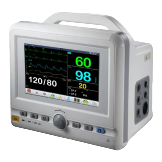
User’s Manual of Patient Monitor Chapter 10 NIBP Monitor ◆ NIBP measurement cannot be carried out on the patients who suffer from the disease of sickle cell, any skin lesion or expecting damage. ◆ It depends on the clinical evaluation that whether auto NIBP measurement is used to measure the patients with serious obstacle of hemoglutination mechanism or not. - Page 83 User’s Manual of Patient Monitor 10-1 NIBP parameter 1— NIBP hotkey: Select the hot key to enter "NIBP Settings" menu 2— Blood pressure alarm off; 3— Pressure time last time 4—Unit of pressure: mmHg/kPa (optional). 5-- The current cuff pressure 6-- Systolic blood pressure values of 120 / 80 diastolic blood pressure values, the average pressure values of 90.
- Page 84 User’s Manual of Patient Monitor 3. Make sure that the cuff is deflated completely. Place the cuff in the patient's upper arm or leg. The sign of φ should be placed on the proper artery. 4. Make sure that wrapping the pantomime with the cuff is not too tight, or else the color in remote part of the limb will change, and even the patient will be lack of blood.
- Page 85 User’s Manual of Patient Monitor “system setup”. The system will change measurement interval according to the setting.
- Page 86 User’s Manual of Patient Monitor ◆ If the measurement time in auto mode is too long, there will be some problems such as purpura, ischemia and neurologic damage on the limb rubbing with the cuff. The color, temperature and sensitivity of the remote part of the limb should be checked during monitoring.
- Page 87 User’s Manual of Patient Monitor condition makes seeking wave difficult, the measurement value will not be reliable and the measurement time will increase. The user should recognize that following cases will affect the...
- Page 88 User’s Manual of Patient Monitor measurement method, make the value uncertain and prolong the measurement time. In such conditions, the measurement cannot be carried out. ◆ Patient movement If the patient is moving, shaking or going into convulsions, the measurement will not be reliable or even impossible.
- Page 89 User’s Manual of Patient Monitor ◆ Alarm level: “High”, “Medium”, “Low”. "High" indicates that the most serious alarm. ◆ Alarm Record: On: the recorder output when the NIBP alarm occurs.
- Page 90 User’s Manual of Patient Monitor Off: no recorder output when the NIBP alarm occurs. ◆ Systolic pressure Limit: To set the trigger limit of systolic pressure value. ◆ Mean pressure Limit: To set the trigger limit of mean pressure value. ◆...
- Page 91 User’s Manual of Patient Monitor ◆ The option "Pre-inflated value" is to help the user to select the next cuff inflation pressure. However, a subsequent measurement of the pre-inflation value is based on the same patient’s systolic blood pressure measurements. Systems can memory the data to reduce the measurement time of the same patients, and increase the accuracy of the measurement.
- Page 92 User’s Manual of Patient Monitor 10-3 NIBP calibration diagram ◆ NIBP measurement calibration should be once every two years (or by statute for the maintenance of your hospital.) ■ Leak detection steps are as follows 1. connected the cuff and the monitor; 2.
- Page 93 User’s Manual of Patient Monitor when inflate, is different from the EN1060-1 standard content. ■ Default configuration : Select this to enter the NIBP default configuration dialog box.
- Page 94 User’s Manual of Patient Monitor 10.4 NIBP alarm information and remind information When the alarm records related to the menu switch is turned on, the physiological alarm which caused by parameters beyond alarm limit will trig the recorder automatically output the alarm parameter and relevant measurement waveform.
- Page 95 User’s Manual of Patient Monitor cuff inflatable Cuff, hose or connector Check and replace leaking parts, if needed , notify the biomedical tube leak damaged engineer or maintenance staff. pressure Pressure is not stable, Check whether hose is tangle, if fault such as hose tangles the problem continued, notify the...
- Page 96 User’s Manual of Patient Monitor Automatic measure... automatic measure process Press start key choose test blanking time in menu Stop test… press start key in measuring process Correct… in correct process Stop correct correct process has finished Leakage test… in leakage testing Stop leakage test…...
- Page 97 User’s Manual of Patient Monitor In order to fix the rubber tube into the cuff again, firstly put the rubber tube on the head of the cuff so that the rubber tube and the big opening of the cuff are in one line. Then roll up the rubber tube lengthways and insert into the big opening of the cuff.
-
Page 98: Chapter 11 Temperature Monitor
User’s Manual of Patient Monitor Chapter 11 Temperature monitor 11.1 summarize The patients’ temperature data can be measured by the temperature probe and display the results in TEMP parameter area, as shown on 11-1 Figure11-1 TEMP parameter 1— TEMP hotkey: press hotkey to enter TEMP setting menu 2—... - Page 99 User’s Manual of Patient Monitor ◆ please check if the probe cable is available before testing. Take out the temperature probe cable of channel 1 from the socket. The screen will display mistake message“T1 sensor is take off” and give an alarm. Other channels are similar. ◆Handle temperature probe and cable carefully.
- Page 100 User’s Manual of Patient Monitor Set up upper limit alarm and Low Alarm Limit in trigger channel 2 Adjustment range of alarm limit:...
- Page 101 User’s Manual of Patient Monitor parameter highest raised to lowest descend to regulating variable limit limit once T1,T2 ◆ TD upper limit alarm Set up upper limit alarm of temperature difference between trigger channel1 and trigger channel2. T1 upper limit alarm: set up upper limit alarm in trigger ◆...
- Page 102 User’s Manual of Patient Monitor ◆ Power down before clean the patient monitor and its connecting sensor. Temperature probe used repeatable...
- Page 103 User’s Manual of Patient Monitor ◆ the heating temperature of the temperature probe could not be beyond 100℃. The probe could bear the short-time temperature 80℃. ◆ the probe cannot be sterilized with steam. ◆ it can be disinfected with detergent containing alcohol. ◆...
-
Page 104: Chapter 12 Co2 Monitoring
User’s Manual of Patient Monitor Chapter 12 ETCO2 monitoring 12.1 summaries ◆ This chapter should only applies to take CO2 monitoring function of the monitor. For example: 12 "portable monitor and 15’’slim type monitor. The monitor is able to measure the patient of CO2 gas (carbon dioxide) pressure, and co2 waveforms in waveforms area. - Page 105 User’s Manual of Patient Monitor ◆ Collision and vibration of CO2 module should be avoided as far as possible ◆ The environment which CO2 concentration is too high (>0.5) may lead to errors ◆ Don’t use the instrument in a flammable gas anesthesia environment ◆...
- Page 106 User’s Manual of Patient Monitor ◆ If the package or internal parts are damaged, please don’t use the accessories and return it to the supplier ◆ When it display “Co2 warming-up” or Co2 transfer warming-up”, that means the transfer is warming and initiating. Measurement cannot be carried out until this messege is disappeared from display ◆...
- Page 107 User’s Manual of Patient Monitor measured value is normal. The screen will display “CO2 too low” when the measured value is lower than lower limit. This message will disappear when the measured value is normal. INS alarm upper limit Used to adjust the InsCO2 alarm upper limit. The screen will display “INS too high”...
- Page 108 User’s Manual of Patient Monitor Calculating circle Three options: A breath, 10 seconds, 20 seconds Calibration refer to chapter 11.3.1.1 12.3.1.1 calibration In the “CO2 other settings” menu, choosing “calibration” can enter the menu as following shows, Figure 12-4 calibration In this menu, users can set these items: Calibrate gas Two options: nitrogen, indoor air Attention...
- Page 109 User’s Manual of Patient Monitor AWRR too high AwRR value higher than alarm upper limit optional AWRR too low AwRR value lower than alarm upper limit optional CO2Breathing high Breathing stop(In setting the time delay not suffocation detect the breathing) ——Tip information Tip information causes...
- Page 110 User’s Manual of Patient Monitor CO2forward flow high anomalies CO2 function disorder high CO2 pressure is high high CO2 pressure is low high please stop using the CO2 communication function, and notice biomedical CO2 module high error engineer maintenance personnel. Co2 module not CO2 initiating error insulted properly...
-
Page 111: Chapter 13 Ibp Monitor
User’s Manual of Patient Monitor Chapter13 IBP monitoring 13.1 The illustration of IBP monitoring This chapter mainly introduce the monitoring of IBP and the maintainance and cleaning of its accessories. Portable monitor can provide two channels for measuring the pressure of blood vessel.(diastolic pressure, mean pressure, systolic pressure). - Page 112 User’s Manual of Patient Monitor ◆ Please check it before using the pressure transducer. It should have no damages and sterilization should be effective. ◆ Zero calibration must be carried out before the measuring, or it will lead to errors of measurement.
- Page 113 User’s Manual of Patient Monitor ◆ If bubble appear in the pressure tube or transducer, then using infusion liquid flushing system. ◆ Before each use, each channel must has "zero pressure calibration. 4) Put transducer on the same level of heart. It’s about located on axillary center line. 5) Make sure you've chosen the right mark name.
- Page 114 User’s Manual of Patient Monitor Chart 13-3 IBP setting menu...
- Page 115 User’s Manual of Patient Monitor For the following content can be setted: ◆ Alarm switch : when choose “open” button, the alarm will provide alarm promot and storage. However, when choose “close”, alarm will not work screen have IBP tips. ◆...
- Page 116 User’s Manual of Patient Monitor Chart 13-4 Alarm line setting In this sun menu, you can set respectively channel 1 and 2 of the systolic blood pressure and diastolic pressure alarm and average with low limit upper limit. When measured value beyond alarm limit, the trigger alarm.
- Page 117 User’s Manual of Patient Monitor The blood pressure waveforms are given to gauge the waveform area. Each waveform’s three dotted line represent the waveform of upper limit on rod, reference ruler, and low limit rod from top to bottom. The three gauge of value can be set and specific methods will be introduced in this menu.
- Page 118 User’s Manual of Patient Monitor Chart13-7 IBP other settings Press the "IBP zero pressure" to popup menu shown below: Figure 13-8 IBP zero pressure ◆ Users should ensure that the sensor before in the measurement have made the zero calibration, otherwise the instrument is not effective zero value, which will result in inaccurate measurements.
- Page 119 User’s Manual of Patient Monitor problem persists, please contact our service personnel. ◆ "The pressure is out of range, can not be zero!" Confirm tee switch to atmosphere, then zero, if the problem persists, replace the sensor, and with the factory for service. ◆...
- Page 120 User’s Manual of Patient Monitor 13.4.3.2 IBP pressure calibration In the menu, press the "IBP pressure calibration" popup menu shown below: Figure 13 9 IBP pressure calibration menu 13.4.3.3 Calibration Sensor: Turn the knob, move the cursor to "Channel 1 pressure calibration value" items, press and turn the knob to select the calibration value, and then move the cursor to "calibrate"...
- Page 121 User’s Manual of Patient Monitor ◆ patients in care, do not be pressure sensor calibration. ◆ Medical institutions should establish regular maintenance and calibration requirements plan, at least once a year IBP pressure calibration. ◆ After unused for long, such as the re-use should be carried out for IBP pressure calibration.
- Page 122 User’s Manual of Patient Monitor Confirm the current pressure values blood pressure is constant, then the calibration. If the error persists, please contact the factory service personnel.
- Page 123 User’s Manual of Patient Monitor 13.3.5 Default Configuration In the "IBP Settings" menu, select "Default Configuration" as shown in Figure 13-11 to enter the default configuration menu: Figure 13-11 Default Configuration Select "Yes", use the system default configuration. Select "No", give up this operation, the system configuration of the original content remains unchanged.
- Page 124 User’s Manual of Patient Monitor IS2 is TOO LOW Channel systolic blood pressure User-selectable measurements below the set lower limit alarm ID2 is TOO HIGH Channel diastolic blood pressure User-selectable measurements above the upper limit set alarm ID2 is TOO LOW Channel diastolic blood...
- Page 125 User’s Manual of Patient Monitor IBP Measurement Stop using module failure or measurements, biomedical IBP(1,2) COM ERR High communication engineers or notify maintenance failure personnel of the company. IBP1 ALM LMT ERR Functional security Stop using IBP alarm to notify the failure Company biomedical...
- Page 126 User’s Manual of Patient Monitor wipe the sensor with water film. Sensors and cables can be cleaned listed below with the soap and detergent to scrub and soak in order to achieve the purpose of cleaning. Cetylcide Wavicide-01 Wescodyne Glutaraldehyde Vesphene Any of the couplings can not be immersed in liquid.
- Page 127 User’s Manual of Patient Monitor...
-
Page 128: Chapter14 Common Troubleshooting
User’s Manual of Patient Monitor Chapter14 Common Troubleshooting ◆ If instruments have some faults in the process of using, users can check the machine according the following methods. If the fault is still not out, please contact with local sales or factories. - Page 129 User’s Manual of Patient Monitor 14.4 Blood pressure and SPO2 have no results ◆ Check if the cuff is on the right place according to the specifications and whether it have leakage. Besides, air tube panel is connected to NIBP socket fixedly or not. Users can do leak detection in the blood pressure settings.
- Page 130 User’s Manual of Patient Monitor ◆ please contact the manufactures if all above steps are confirmed and measurement still can’t be carried out. 14.5 Monitor invalid state performance Attention When the monitor ECG is invalid, the screen will display “signal saturation”. ◆...
-
Page 131: Chapter15 Specifications
User’s Manual of Patient Monitor Chapter15 Specifications 15.1 Type of the patient monitor Classifications of Electric shock guard: Class I EMC: A Scale are B Classifications of Electric shock guard: ECG is CF model;TEMP,SpO2、 NIBP、 ETCO Fmodel Liquid-proof extent: general hermetically sealed instrument, not having the function to prevent the liquid access. - Page 132 User’s Manual of Patient Monitor Informations: The interface have 8 word waveforms display, Trend Graph, Big Font, OxyCRG, and Standard. Level 3 sound , light and electricity alarm and system hints Power indicator and the remote control receiving instructions (green/orange) A working indicator light (green) A charging battery indicator light (yellow) and owe pressure system hints 15.4 Interface...
- Page 133 User’s Manual of Patient Monitor 4.3.1.2 Auxiliary output (if provide) Not applicable No damage in short circuit state 4.3.1.3 Breathing, lead united fall off detection exist and active noise suppression Active guide united direct current maximum µA 4.3.1.4 QRS wave monitoring 4.3.1.4.1 QRS range of wave and width are conformed with 4.2.6 standard...
- Page 134 User’s Manual of Patient Monitor 4.3.1.6.6 Starting time of heart rate high alarm maximum 4.3.1.6.7 Alarm mute Provide mute restart configuration 4.3.1.6.8 Alarm banned Fit the requirement of 4.2.7.8 in YY1079-2008 4.3.1.7 Special requirements of monitors that have the ability of ECG waveform display 4.3.1.7.1 Dynamic range input Signal range input...
- Page 135 User’s Manual of Patient Monitor Lagging effect after 15mm migration maximum Addition Standard Required description minimum/ unit Minimum/m item maximum aximum values Refer to YY1079 的 4.2.8.9 4.3.1.7.9 Calibration voltage 4.3.1.7.10 Common mode rejection allowed 10 V maximum industrial frequency noise 4.3.1.7.11 Baseline control and stability Recovery time after reset...
- Page 136 User’s Manual of Patient Monitor 150mmHg to 5mmHg (neonate) 4.3.4.2 Performance requirement 4.3.4.2.1 Measuring range range mmHg 0~260 4.3.4.2.2 Resolution minimum mmHg 4.3.4.2.3 maximum mmHg ±4 error(repeatability) 4.3.4.2.4 Precision of pressure sensor maximum mmHg ±3 4.3.4.3.1 Time that air source provide enough air to maximum make the pressure of 200cm3 condition become 40kpa...
- Page 137 User’s Manual of Patient Monitor Alarm lower limit minimum mmHg 20~108 of MEAN Alarm upper minimum mmHg 12~100 limit of DIA Alarm lower limit minimum mmHg 10~98 of DIA 4.3.5 SPO2 section 4.3.5.1 Range of measurement range 40~100 4.3.5.2 maximum (90%~99%)the precision(error)...
- Page 138 User’s Manual of Patient Monitor 4.3.8.3 Remote device Exist 4.3.8.4 Sound pressure level of The range of peak value is between 445dB audition alarm to 85dB in 1m length. Adjustable 4.3.8.5 Recovery of defibrillation and Discharge in 1min, monitor work normally。 discharge 4.3.9 Normal working state...
- Page 139 User’s Manual of Patient Monitor Chapter 16 Install for Bracket This chapter introduce the standard of the installation and adjustment support content for the ■ 12 inch and 15 inch silm type monitor Please according to the following content for the installation of the wall bracket, the wrong ■...
- Page 140 User’s Manual of Patient Monitor 16.2.2 L-2 and WLB011 type bracket specifications ◆ Bracket type:L-2 or WLB011; ◆ Bearing ability:15kg; ◆ Scope from professional application: Wall, Car; ◆ Positioning hole size:75*75mm or 100*100mm; ◆ Level rotation Angle:180°; ◆ Vertical rotation Angle:180°; ◆...
- Page 141 User’s Manual of Patient Monitor 16.3 Other description for bracket 16.3.1 JHQ type bracket Specifications ◆ Bracket type:JHQ; ◆ Bearing ability:20kg; ◆ Scope from professional application: Wall, Car; ◆ Positioning hole size:75*75mm/127*31mm/145*80mm; ◆ Level rotation Angle:360°; ◆ Vertical rotation Angle:30°; 16.3.3 TRC type bracket Specifications ◆...
- Page 142 User’s Manual of Patient Monitor...
- Page 143 User’s Manual of Patient Monitor Graph 2: (WLB011)Bracket installation diagram:...
- Page 144 Graph 3:JHQ Assembly diagram Graph 4:TRC Assembly diagram...
Need help?
Do you have a question about the 12.1 inch portable and is the answer not in the manual?
Questions and answers