Table of Contents
Advertisement
Quick Links
Advertisement
Table of Contents

Summary of Contents for AT BF5
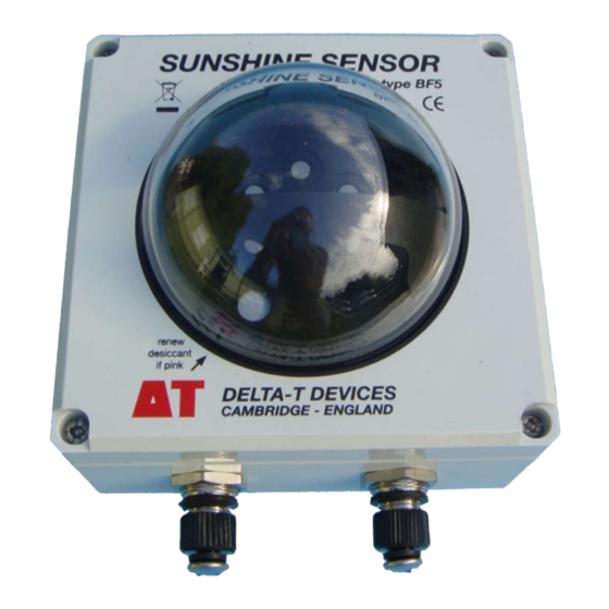
- Page 1 User Manual for the Sunshine Sensor type BF5-UM-2.3 Delta-T Devices Ltd...
-
Page 2: Notices
Ltd. Under the law, copying includes translation into another language. Copyright © 2022 Delta-T Devices Limited BF5 Sunshine Sensor optics design and theory are Copyright © 1996 John Wood, Peak Design & Development, Winster, Derbyshire, U.K. and protected by Patent Nos. EP1012633 & US6417500. -
Page 3: Table Of Contents
Connecting to SunScan Environment and Moisture protection Use with a data logger Effect of engineering units on sensitivity and resolution Sunshine Status Output Analogue outputs Simplified output schematic Suggested power supply connections BF5 User Manual v 2.3 Contents 3... - Page 4 BF5 Accuracy and Resolution Other specifications BF5 Components Specifications BF5 - SunScan Cable BF5 Logger Cable BF5 Analogue Extension Cables Can be used to extend both BF5-Sunscan cable and BF5-Logger Cables RS232 Serial Cable Serial Extension Cable Telescopic Tripod Cross Arm for Mast Mount...
- Page 5 Molar units (mol.m Energy units (W.m Illuminance units (lux) Sunshine state Glossary Index BF5 User Manual v 2.3 Contents 5...
-
Page 6: Introduction
See also the SunScan documents on the Software and Manuals DVD. Appendix 1 describes the BF5 design and includes a summary of the test results of several experimental trials of its predecessors, the BF3 & BF2. See also: BF5 Quick Start Guide... -
Page 7: What It Is Used For
Use with a data logger The three outputs of the BF5 can be logged with a suitable data logger. The Total and Diffuse radiation millivolt outputs require two analogue channels. The use of a data logger with differential sensor inputs (rather than single-ended) is recommended. -
Page 8: Use With Sunscan
The BF5 is a powered sensor. For power economy, the BF5 can be woken up via a warm-up signal from the data logger. ... -
Page 9: Construction
Whenever the temperature drops below 5C the heater is increased, to full power below 0C - to remove snow or ice. At zero wind speed a BF5 at minus 20C will become snow and ice free in 30 minutes once power is applied to the heater. - Page 10 Cable connectors and components inside the dome Section through BF5, showing internal PCBs and battery pack 10 Introduction BF5 User Manual v 2.3...
-
Page 11: Accessories
Accessories Mounting Mount the BF5 to a camera tripod if using it close to, or above low field canopies (i.e. up to about 1.8m. A standard camera tripod socket is mounted in the base of the BF5 for this purpose (¼ inch Whitworth x 8mm). -
Page 12: Power Considerations
Power Considerations The BF5 is a powered sensor. There are four possible sources of power: The internal 3V alkaline batteries, if fitted. These are optional. Power from the data logger. This only needs to be applied when the logger takes a reading. The BF5’s Total, Diffuse and Sun analogue outputs are valid 100ms after power is applied, and are then updated every 250ms. -
Page 13: Heater
Power from the PC’s serial port (but not some laptops). The BF5 draws power from the PC DTR signal. Most computer serial ports will provide enough power for the BF5 sensor electronics (but not its heater). If more than one of these sources is present, then power is generally taken from the source with the highest voltage. - Page 14 At zero wind speed the dome will remain snow and ice-free down to minus 20C. At 2m.s wind speed the dome will remain snow and ice-free down to minus 10C. In air temperatures below 5 C the heater can consume 1.5A at 12V DC so a 40 Ah car battery will only last about one day.
-
Page 15: Getting Started
See also BF5 Quick Start Guide In the field you need something on which to mount the BF5 horizontally. Use a camera tripod, e.g. type BFT1, or Bolt onto a suitable horizontal surface using the four M4 bolt holes in the base of the BF5 plastic housing, or ... -
Page 16: Connect Your Bf5
The Serial port menu indicates which COM ports are available on the PC, with a check mark for the one selected. Once a port is selected, it will be interrogated periodically until a BF5 is found, then the version information will be displayed, and power supply voltage and readings will be updated every few seconds. -
Page 17: Preliminary Checks
It should be blue. If pink, replace the internal bag of desiccant. To renew the desiccant, see Page 35. When you first use the BF5 in the field, check that it is reading in the right engineering units, and that the values seem reasonable. Check the Dome The BF5 dome must be clear and unmarked for accurate measurements. -
Page 18: Use With Sunscan
Use with SunScan Setting up the BF5 The BF5 is simple to operate. Make sure the BF5 output units are set to the PAR molar units (mol m ) using SunRead. As a general guide, the above-canopy reference measurements should be... -
Page 19: Environment And Moisture Protection
Internal condensation will be avoided if you keep the desiccant fresh. Inspect the desiccant indicator inside the dome. It should be blue. The BF5 is reasonably robust, but does not have a drop test rating. Do not drop it. BF5 User Manual v 2.3... -
Page 20: Use With A Data Logger
Use with a data logger The BF5 may be connected to an external data logger with readings being taken continuously. The BF5 updates its output values four times per second. A logger with differential sensor inputs (rather than single-ended) is recommended. -
Page 21: Analogue Outputs
Analogue outputs Connect the BF5 to a data logger via the 8-pole M12 waterproof connector using cable type SP-BF/w-05. See also Cables on page 11. Additional weatherproof extension cables with M12 connectors at each end are also available (type EXT/8w-x where x = 5, 10 or 25m). -
Page 22: Simplified Output Schematic
Note The various grounds (Htr-, DL-Gnd, Signal Gnd) are all connected at the BF5, so if the heater is in use, then the Signal Gnd must be able to float relative to the two power grounds at the logger end. -
Page 23: Suggested Power Supply Connections
The serial port lines have basic ESD protection. Suggested power supply connections For use with a data logger, the DL-Power line has to be at 5V or more to enable the analogue outputs. The power required can be taken either from the DL-Power line, or the heater supply. - Page 24 The key point is that the various grounds (Htr-, DL-Gnd, Signal Gnd) are connected at the BF5, so if the heater is in use, then the Signal Gnd must be able to float relative to the two power grounds at the logger end.
-
Page 25: Suggested Sun Output Connections
Suggested Sun output connections There are several possible ways of connecting up the BF5 Sun output, depending on the capabilities of your data logger. The Sun output is open circuit when there is no sun, and connected to ground when there is sun. - Page 26 DL-Gnd wire, and not the SigGND wire, otherwise you may see large offset voltages on your Total and Diffuse readings. 26 Use with a data logger BF5 User Manual v 2.3...
-
Page 27: Ground And Screen Connections
In general the screen (black wire) should be connected to local earth near the logger. The BF5 may also be connected to earth at its mounting point. If there is a lightning strike nearby, there may be large transient voltages induced between earth points, and in the sensor cabling. -
Page 28: Delta-T Data Logger Connections
BF5. The input voltage range is insufficient and we provide no SPN1 sensor types or program for Warning: Do not attempt to attach a BF5 to a DL6 via the 8 pole M12 connector on the DL6. It may damage the sensor. -
Page 29: Technical Reference
0.060 klux 0-2500 mol.m Range 0-1250 W.m 0-200 klux Analogue output 1mV = 1mV = 1mV = sensitivity 1 mol.m 0.5 W.m 0.100 klux Analogue output 0-2500mV 0-2500mV 0-2000 mV range BF5 User Manual v 2.3 Technical reference 29... -
Page 30: Other Specifications
Signal output & power-in connector 8 pin M12 Mounting options: Camera tripod socket (¼inch Whitworth) Holes for 4 x M4 bolts at corners of box. Size & Weight 120mm x 122mm x 95mm, 635g Heater output below 0C 15 W Heater output above 5C... -
Page 31: Bf5 Components Specifications
8-pin M12 male connector to combined power and signal cable to bare wires for logger terminals and/ or heater power supply. BF5 Analogue Extension Cables Can be used to extend both BF5-Sunscan cable and BF5-Logger Cables Type EXT/8w-05 Length Termination... -
Page 32: Serial Extension Cable
1 ¼ x 2 inch, KeeKlamp type 45-86 Saddle washers Bolt 1 ¼ inch long x ¼ inch BSW stainless steel hex. head Adjustable Camera Mount 1/4 inch BSW (camera) thread, with ball clamp Allen key 8mm A/F 32 Technical reference BF5 User Manual v 2.3... -
Page 33: Cosine Response
Cosine response Cosine Response BF5 Actual/ Ideal Ideal cosine reponse BF5 actual response Zenith angle in degrees BF5 User Manual v 2.3 Technical reference 33... -
Page 34: Spectral Response
Spectral response 34 Technical reference BF5 User Manual v 2.3... -
Page 35: Routine Maintenance
To regenerate the desiccant. The desiccant pack can be regenerated by heating. Remove the pack from the BF5 and heat in an oven for a few hours at about 90ºC. Allow it to cool down away from moisture before reinstalling it. - Page 36 36 Technical reference BF5 User Manual v 2.3...
- Page 37 It is possible to recalibrate the BF5 yourself against a transfer standard sensor, but this is difficult and not recommended. You will need stable sunlight or a stable sunlight simulator. Natural atmospheric turbulence can cause rapid variations in sunlight intensity, which, if greater than the quoted accuracy of the BF5, could make it impossible to recalibrate in sunshine.
-
Page 38: Warranty And Service
Delta-T shall not be liable for the cost of carriage or for customs clearance in respect of such goods. However, we much prefer to have such returns discussed with us in advance, and we may, at our discretion, waive these charges. -
Page 39: Service And Spares
No goods or equipment should be returned to Delta-T without first obtaining the agreement of Delta-T or our distributor. On receipt at Delta-T, the goods will be inspected and the user informed of the likely cost and delay. We normally expect to complete repairs within a few working days of receiving the equipment. -
Page 40: Problems
Details of any PC you are using Software version numbers and hardware serial numbers (see below) Locating version and serial numbers The BF5 serial number label is on the underside of the case. The internal software version number is displayed in the About box using SunRead. -
Page 41: Appendix A: Design And Test Summary 41
Appendix A: Design and Test Summary This appendix gives a brief description of how the BF5 design works, and a summary of the results of the test program. More detailed versions of these are available from Delta-T and on the Software and Manuals DVD. -
Page 42: Calculation Of Outputs
Conversion to appropriate units Molar units (mol.m The photodiodes used in the BF5 have a spectral response that is close to an Ideal PAR response (see spectral response graph in the Technical Reference section). The BF5 is calibrated using a reference quantum sensor, so calculates its output values in PAR units. -
Page 43: Illuminance Units (Lux)
However, the spectral distribution of Diffuse light does vary considerable between blue sky and overcast conditions. To take this into account, the BF5 uses the Beam Fraction (Direct / Total) as an estimator of the proportion of blue skylight, and applies a conversion dependent on this value. - Page 44 This graph shows a comparison of a BF2 against two Delta-T quantum sensors and a shade ring. Data recorded at Winster, Derbyshire, 20 – 31 May 1999. The graph plots hourly averages of readings every 5 seconds. Note the offset Y-axis to separate the Total and Diffuse plots.
- Page 45 This graph shows BF3 Total and Diffuse outputs compared with two Kipp CM11s and a shade ring. Data recorded at Napier University, Edinburgh between February and July 2001. The graph plots hourly averages of readings every 10 seconds. Note the offset Y-axis to separate the Total and Diffuse plots.
- Page 46 LiCor klux This graph shows a comparison of a BF3 (Total output) against a LiCor Illuminance sensor. Data recorded at Burwell, Cambridge, UK 16 – 23 Aug 2001. The graph plots 5 minute averages of readings every 5 seconds. 46 Appendix A: Design and Test Summary...
- Page 47 This graph shows daily sunshine totals measured by a BF3, compared to the WMO definition of 120 W.m-2 in the Direct beam. Data recorded at Napier University, Edinburgh between February and July 2001. Comparable data from an adjacent Campbell-Stokes recorder is also plotted.
-
Page 48: Glossary
Beam fraction- the fraction of Total incident radiation in the Direct beam. Beam Fraction Sensor (BFS) - A device for measuring Direct and Diffuse light above the canopy. Types BF3 and BF5 consist of seven PAR sensors and an acrylic dome with stripes. They also measures sunshine hours. -
Page 49: Index
Copyright klux Cosine response 33, 49 Latitude 7, 30 Data logger Leaf Area Index Use with Levelling Desiccant 17, 35 Logging Diffuse light Longitude Direct beam DL2e Logger DL6 Logger BF5 User Manual v 2.3 Index 49... - Page 50 Response time RS232 Warning Cleaning the dome screen connection Warranty options Weather Station Sensitivity Wiring Serial numbers analogue signals and heater power Serial port Service and Spares software Specifications Zenith angle Spectral response 50 Index BF5 User Manual v 2.3...
Need help?
Do you have a question about the BF5 and is the answer not in the manual?
Questions and answers