Table of Contents
Advertisement
Advertisement
Table of Contents

Summary of Contents for iRAYPLE L5082MG170E
- Page 1 Line Scan Camera User’s Manual V1.0.0...
-
Page 2: Foreword
This manual introduces the functions and operations of the line scan camera (hereinafter referred to as "the camera"). Model L5082MG170E, L5082MK170E, L5022MG141E, L5022CG141E, L5042MG141E, L5042CG141E, L5027MG140E, L5027CG140E, L5047MG140E, L5047CG140E Safety Instructions The following signal words might appear in the manual. - Page 3 All designs and software are subject to change without prior written notice. Product updates might result in some differences appearing between the actual product and the manual. Please contact customer service for the latest program and supplementary documentation. There might be errors in the print or deviations in the description of the functions, operations ...
-
Page 4: Important Safeguards And Warnings
Important Safeguards and Warnings This section describes the content covering proper handling of the device, hazard prevention, and prevention of property damage. Read these contents carefully before using the device, comply with them when using, and keep the manual well for future reference. Operation Requirements Transport, use and store the device under allowed humidity and temperature conditions. -
Page 5: Table Of Contents
Table of Contents Foreword ................................I Important Safeguards and Warnings ......................III 1 Product Information ............................1 Product Overview ..................................1 Product Features ..................................2 1.2.1 CameraLink Line Scan Camera ..........................2 1.2.2 GigE Line Scan Camera ............................... 2 Typical Networking ..................................2 Application Environment ................................ -
Page 6: Product Information
Product Information Product Overview The line scan camera is a highly reliable and cost-effective camera for industrial use. It can be divided into CameraLink line scan camera and GigE line scan camera according to the interface. The CameraLink line scan camera uses a high-performance photosensitive chip and transmits ... -
Page 7: Product Features
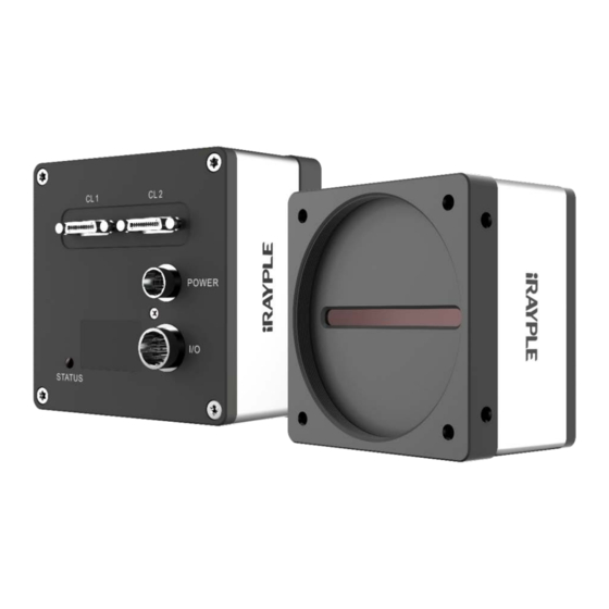
Figure 1-2 Appearance (GigE) Product Features 1.2.1 CameraLink Line Scan Camera Simple installation and convenient operation. Supports Deca, Full, Medium, Base, and theoretically, it can provide up to 6.8 GB/s bandwidth. Multiple trigger modes such as external trigger, free-run, multi-frame trigger, and more. ... -
Page 8: Application Environment
Figure 1-3 Networking Application Environment Temperature and humidity. The ambient temperature cannot exceed 50 °C, and it is best to for the camera to work in an air-conditioned environment. Ambient temperature when the camera is working: –30 °C to +50 °C. ... -
Page 9: Mv Viewer Installation And Camera Connection
MV Viewer Installation and Camera Connection Downloading and Installing MV Viewer Step 1 Go to http://download.huaraytech.com/pub/sdk/. Step 2 Select version, and then select operating system. Download the package, and then install the package on your PC. Figure 2-1 Select version Connecting Camera Step 1 After installation, open MV Viewer. - Page 10 Parameter Description Includes video stream, image stream, display stream, image position, Image settings grayscale, RGB color value, and more. : Play/pause. You can click on the right side to select from continuous, single-frame, and multi-frame modes. You can switch play modes only when play is paused. : Save one or multiple pictures.
- Page 11 Menu Description Language Language Chinese and English are available.
-
Page 12: Function Parameters
Function Parameters This chapter mainly introduces the functional parameters related to industrial cameras. Industrial cameras support three user levels: Beginner, Expert, and Guru. Parameters relating to each level are slightly different. Parameters in black shade can be changed or edited, and parameters in gray shade cannot be ... - Page 13 Connect the camera through MV Viewer, and then select Features > AcquisitionControl. Step 1 Step 2 Select AcquisitionLineRate, and then you can view the maximum and minimum line scan rate, and also adjust the rate. If the maximum line scan rate of the camera is lower than the defined rate, the camera ...
-
Page 14: Frame Timeout
Frame Timeout In the frame + line mode, when the number of line signals has not reached the defined line height, the image will be displayed only after the subsequent line signals reach the defined line height. In special circumstances, if the line signal does not reach the defined line height, the camera will wait for the subsequent line signal. -
Page 15: Trigger Mode
Table 3-1 Description of acquisition frame parameters Parameter Description SingleFrame After starting acquisition, the camera only captures one image. After starting acquisition, the camera captures images consecutively. When the number of acquisition lines reaches the height of the image, one ... - Page 16 FrameActive: A high-level (low-level) area captures multiple lines, and an image will be generated until meeting the defined line height. If the defined line height is not met, the image will be directly generated according to the captured line height. Figure 3-10 FrameActive FrameBurstActive: Multiple images can be outputted within a trigger signal high level (low...
-
Page 17: Trigger Source
FrameBurstStart: Multi-frame mode of frame trigger mode. Outputs multiple images according to the define line height after receiving a trigger signal rising edge (falling edge). The number of images depends on the value defined in TriggerFrameCount. Figure 3-12 FrameBurstStart Line + frame trigger: When there are multiple trigger signals, you can enable frame trigger and ... - Page 18 Capture card trigger: A unique trigger mode of CameraLink line scan cameras. External signals enter the camera through the capture card, and the capture card sends the signals to the camera through the CameraLink cable for triggering detection. Figure 3-14 Capture card trigger Trigger signal includes RisingEdge and FallingEdge.
- Page 19 For example, if Line1 is used as the input source of direction A, then connect A+ to the red line (Line1+), connect A- to the black line (Line1-). If Line2 is used as the input source of direction B, then connect B+ to the blue line (Line2+), and connect B- to the orange line (Line2-).
- Page 20 3.4.2.2 Frequency Division and Multiplication Control 3.4.2.2.1 Introduction You can manage the frequency division and multiplication function of the signal source. For signal sources after frequency division, the frequency will become slow. For signal sources after frequency multiplication, the frequency will become faster. When external signals trigger the camera to start working, the image effect might be poor, or the image might be severely stretched or compressed.
-
Page 21: Trigger Delay
Similarly, when the image is stretched, you can adjust the divider value. Figure 3-20 Adjustment results Trigger Delay Delay time can be set between the time that the camera receives trigger signal and the time that the camera captures an image. The camera captures an image after the defined trigger delay. Figure 3-21 Working principle of trigger delay You can configure Trigger Delay. -
Page 22: Non-Isolated Differential Signal
3.6.1 Non-isolated Differential Signal Connected to incremental rotary encoder with differential output. Often used as a line trigger signal input. We recommend using a differential output (linear drive output) encoder for long-distance transmission. Step 1 Connect the A/B phase output of the encoder to the Line+ pin of the camera, and then to the Line–... - Page 23 Figure 3-24 Encoder with non-isolated single-ended signal For NPN collector output, it is required to connect a pull-up resistor between the encoder power supply (VCC) and the signal cable. For PNP collector output, connect a pull-down resistor between the encoder power ground (0 V) and the signal cable. The resistance value is generally between 1–10 K, depending on the power supply voltage of the encoder.
-
Page 24: Isolated Single-Ended Signal
3.6.3 Isolated Single-ended Signal It is used to connect the output of photoelectric sensor or other general PLC switch. It often used as frame trigger signal input. Step 1 Connect the output interface of signal source to the optocoupler input, and connect the other end to the optocoupler isolation ground. -
Page 25: Fpn Correction
Figure 3-30 After filtering When the value of LineDebouncingPeriod is greater than the value of high and low levels, as shown in the example above, if the filtering level is greater than 5000 us, the camera will not generate streams. Therefore, when setting LineDebouncingPeriod, make sure that its value is smaller than the high and low level. -
Page 26: Black Level
Black Level Black level helps you adjust the gray value offset of the output data. The gray value offset determines the average gray value when the sensor is not sensitive. For different ADC bit depth modes, the black level parameter ranges of the camera are different. To configure black level, set the Black Level value. -
Page 27: White Balance
3.11 White Balance White balance allows you to adjust the corresponding R/G/B values to compensate for color cast that occurs when capturing images in different light sources. It aims to keep the white areas of the image white at different color temperatures. White balance is divided into three modes: Off, once, and continuous. -
Page 28: Gamma
We recommend that after calibration, you can save the parameters, to prevent recalibration after the camera is powered off and restarted. When the light source and the color temperature of the camera location change, you need to calibrate the white balance again. 3.12 Gamma It is a non-linear correction of the image data due to non-linear response of the display. -
Page 29: Transmission Layer Management (Tap Settings)
3.13 Transmission Layer Management (TAP Settings) 3.13.1 CameraLink Line Scan Camera Transmission Layer Figure 3-41 CameraLink line scan camera transmission layer Table 3-5 CameraLink transmission layer management Parameter Description TapGeomety Arrangement format of camera output images. Configuration Output type, which includes Base, Medium, Deca and Full. It is One by default. -
Page 30: Gige Line Scan Camera Transmission Layer
3.13.2 GigE Line Scan Camera Transmission Layer Figure 3-42 GigE line scan camera transmission layer (1) - Page 31 Figure 3-43 GigE line scan camera transmission layer (2) Table 3-6 GigE line scan camera transmission layer management Parameter Description PayloadSize The length of each message. GevActiveLinkCount The number of logical channels currently connected. GevInterfaceSelector The number of device network ports. It is 0 by default. GevLinkSpeed The negotiated rate of the current network port.
- Page 32 Parameter Description Enable DHCP function. GevCurrentIPconfiguration When setting GevCurrentIPconfigurationDHCP to True, you can DHCP set the IP address in DHCP mode. In this case, the IP address can be automatically obtained. Static IP function. When setting GevCurrentIPconfigurationPersistentIP to True, you can set the IP address in static mode after the device is GevCurrentIPconfigurationP powered on.
- Page 33 Parameter Description GevGVSPExtendedIDMode Enable GVSP extended ID code. Controls the permissions of applications to access the camera. ExclusiveAccess: The application that connected to the camera can GevCCP can modify the register. ControlAccess: The application that connected to the camera can can read the register, but cannot modify it.
-
Page 34: Testimage (Test Mode)
3.14 Testimage (Test Mode) You can set the test mode of the camera. When the camera is in test mode, the camera will not capture images in real time, but images defined in the camera program. When the real-time image is abnormal, you can almost know the reason of the image anomaly by checking whether the image in the test mode has similar problems. -
Page 35: Appendix 1 Rotary Encoder Faq
Appendix 1 Rotary Encoder FAQ What is the difference between voltage output, collector signal output, and differential output of the encoder? The collector signal output uses the transistor emitter of the output circuit as the common end, and the collector is suspended in the output circuit. Collector signal output is generally divided into NPN open collector output and PNP open collector output. - Page 36 Differential output is a data transmission method by using dedicated IC output and based on RS422-A specifications. The signal outputs as a differential 2 signal, so it has strong anti-interference ability, suitable for long-distance and high-speed transmission. The camera side uses a dedicated IC (called RS422 transceiver) to receive the signal sent by the encoder.
- Page 37 What are maximum response frequency and maximum allowed speed? The maximum response frequency is the maximum electrical response frequency of the encoder. The unit is Hz. If the encoder is used not exceeding this parameter, its internal circuit will not be able to respond, resulting in pulse leakage of the encoder. The maximum allowed speed refers to the highest speed that the shaft of the encoder can ...
- Page 38 CW means clockwise rotation, as shown in the figure below. In this rotation direction, phase A of an incremental encoder outputs before phase B. The opposite of the CW rotation direction is CCW (counter clockwise). In this rotation direction, phase B of an incremental encoder outputs before phase A.
-
Page 39: Appendix 2 External Input Interfaces Of Line Scan Camera
Appendix 2 External Input Interfaces of Line Scan Camera Table 3-7 First-generation line scan camera—E2 V 4 K network port and CMOSIS 8 K network port Signal Name Function Remarks Line1_in– RS422 input– Connects the encoder (frame trigger) Line1_in+ RS422 input+/single-end input Connects the encoder (frame trigger) Line3_inout–... - Page 40 Signal Name Function Description Connects the photoelectric switch OPT_IN Line5 Optocoupler input Line5 (line trigger) OPT GND Opto-isolated ground — Use RS-422 input to connect to the encoder, and provide line trigger signal. Use optocoupler input to connect photoelectric switch or PLC output to provide frame trigger ...
-
Page 41: Appendix 3 Line Scan Camera Models
Appendix 3 Line Scan Camera Models Table 3-10 First-generation line scan camera—E2 V 4 K network port and CMOSIS 8 K network port/CL L5082MG170E L5082MK170 E Table 3-11 Second-generation line scan camera—CMOSIS 4 K network port L5022MG141 E L5022CG141 E... -
Page 42: Appendix 4 Cybersecurity Recommendations
Appendix 4 Cybersecurity Recommendations Cybersecurity is more than just a buzzword: it’s something that pertains to every device that is connected to the internet. IP video surveillance is not immune to cyber risks, but taking basic steps toward protecting and strengthening networks and networked appliances will make them less susceptible to attacks. - Page 43 Disable Unnecessary Services and Choose Secure Modes If not needed, it is recommended to turn off some services such as SNMP, SMTP, UPnP, etc., to reduce risks. If necessary, it is highly recommended that you use safe modes, including but not limited to the following services: SNMP: Choose SNMP v3, and set up strong encryption passwords and authentication ...
Need help?
Do you have a question about the L5082MG170E and is the answer not in the manual?
Questions and answers