Table of Contents
Advertisement
Quick Links
Advertisement
Table of Contents

Summary of Contents for iRAYPLE 5000 Series
- Page 1 Binocular structured light 3D camera User Manual V1.0.0 V1.0...
-
Page 2: Foreword
Foreword Overview This article briefly describes the content of the binocular 3D camera, including product introduction, networking, installation and quick operation of application software. Symbol definition The following symbols may appear in the document. Please refer to the table below for the respective definition. Symbol Note It indicates a potentially hazardous situation which, if not avoided, could... -
Page 3: Safety Instructions
Safety instructions The following is about the correct use of the product, in order to prevent danger, prevent property damage, etc., please read this manual carefully before using the equipment and strictly follow it during use. Please keep the manual properly after reading. Requirements •... - Page 4 • Please refer to the actual product. This document is for reference only. • This document is for reference for multiple models of products. The specific operations of each product are not listed one by one. Users are requested to compare and operate according to the actual product. •...
-
Page 5: Table Of Contents
Content Foreword ................................... I Safety instructions ..............................II 1 Product introduction ............................1 1.1 Product introduction ............................ 1 1.2 Product feature ............................. 2 1.3 Packing list ..............................3 1.4 Product structure ............................3 1.4.1 Product dimension ..........................3 1.4.2 Product interface ..........................4 1.5 Electrical specification .......................... -
Page 6: Product Introduction
Product introduction Product introduction The 5000 series binocular 3D camera is an intelligent stereo camera specially developed for customer application requirements such as cargo picking, palletizing and disassembling in docks, warehouses and other environments. The camera realizes 3D detection function based on the principle of triangulation positioning through dual image sensors and speckle laser. -
Page 7: Product Feature
Product feature Built-in high-precision measurement algorithm, high measurement accuracy Small installation space, high integration, Cost-effective product uniform and reliable speckle laser module Superior optical filter design, strong resistance to ambient light Built-in aviation plug, rich IO interface 4 indicator lights for debugging and function display 4 Industrial grade M12 connector, IP65 protection grade Support multi-camera cascade Product specification:... -
Page 8: Packing List
Packing list When unboxing, please check if there is any obvious damage and confirm that the accessories list is consistent Table 1 Packing list with the packing list. For details, see following Table Material Binocular 3D camera Mount plate Power/IO cable GigE network cable M4×10 screw Power adapter... -
Page 9: Product Interface
Figure 2 Dimension of mount plate 1.4.2 Product interface There are two interfaces on the side of the device: 8-pin network interface and 12-pin power supply and I/O Figure 3 Interfaces interface, as shown as follow: Product introduction 4... - Page 10 1.4.2.1 Network interface The camera uses a gigabit network for software parameter setting and 3D image data transmission. The interface form is a waterproof M12 8-pin aviation connector. The product comes with an aviation connector to RJ45 category 6 high flexible network cable. 1.4.2.2 I/O interface Figure 4 Pin-assignment The pin definition of the I/O interface is shown in following igure .
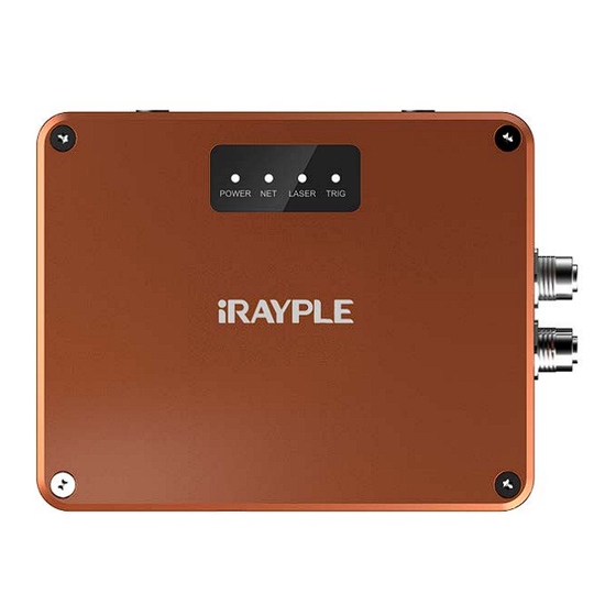
- Page 11 1.4.2.3 Indicator POWER LASER TRIG Power indicator/green Network status Laser enable Trigger status Table 3 Indicator The definition of status is as follow: Status Definition Power on POWER No power Camera connected Camera not connected Laser on LASER Laser off Camera is working(triggering) TRIG Wait for...
-
Page 12: Electrical Specification
Electrical specification Opto-isolated input: The relationship between sink current and input voltage of isolated input port 1 (high speed) is shown in the figure: Input Description +26.0VDC Limit voltage, the input cannot exceed this limit value, otherwise it will cause equipment damage +0~+24VDC I/O safe working voltage range +0~+1.4VDC... - Page 13 Input signal amplitude(Vp-p) Rising edge trigger delay tDR(ns) Falling edge trigger delay tDF(ns) 3.00 5.00 9.00 10.00 Notice: The trigger delay measures the delay from the external opto input port to the FPGA pin input, without considering the FPGA internal logic delay. 2.
- Page 14 Input signal amplitude(Vp-p) Rising edge trigger delay Falling edge trigger delay tDF(ns) tDR(ns) 3.00 25.2 5.00 9.00 10.00 25.6 3. The shortest input positive pulse supported by the opto input is 3.2μs (typical value), and the shortest input negative pulse is 18.0μs (typical value) 。...
- Page 15 Typical application example of opto input: Product introduction 10...
- Page 16 Diagram of wiring PNP type output PLC to camera's opto input Diagram of wiring NPN type output PLC to camera's opto input Opto-isolated ouput: Voltage Description +26.0VDC Limit voltage, the input cannot exceed this limit value, otherwise it will cause equipment damage <+3.3VDC I/O output may be wrong...
- Page 17 The pull-up resistor value selection in the figure should be based on the given voltage, not exceeding the maximum allowable current value of the opto-isolated output port. The larger the pull-up resistor value, the smaller the optocoupler conduction voltage drop, and the longer the output waveform rise and fall time. The smaller the external driving ability.
- Page 18 The relationship between opto output conduction voltage drop (voltage drop between OPT_OUT and OPT_GND) and output current (current flowing into the OPT_OUT pin) is shown in the figure: 2.50 2.00 1.50 1.00 0.50 0.00 Output current (mA) 1. The maximum conduction voltage drop of the opto output is 2.35V (measured at a maximum output current of 100mA).
- Page 19 Importance: If the camera output is connected to an inductive load such as an intermediate relay, it must be a model with a built-in freewheeling diode (or an external freewheeling diode, such as 1N4007), otherwise it will cause instantaneous overvoltage damage to the output interface. Typical application example of opto output: The diagram of connect the camera's opto output to the PLC through the negative common terminal The diagram of connect the camera's opto output to the PLC through the positive common terminal...
- Page 20 Differential input or output: Common mode voltage Description -9/+14VDC Limit voltage, the voltage of the input differential signal to ground cannot exceed this limit value, otherwise it will cause damage to the equipment -8/+13VDC Recommended voltage of input differential signal to ground +2.5VDC Output differential signal to ground voltage Differential Mode Voltage...
- Page 21 Typical sample: Product introduction 16...
-
Page 22: Network
Network The typical networking mode of the product is a point-to-point connection, that is, the PC and the camera are directly connected through a Gigabit Ethernet cable without passing through other network media, as shown in Figure 5 Typical networking following figure Network 17... -
Page 23: Product Installation
Product installation Figure 6 Installation Product installation 18... -
Page 24: Camera Operation
Camera operation Install the client Introduce the installation and function operation of the client. Background Information The PC requirements for installing the client are as follows. The network port connected to the camera must be a gigabit network port Pre-condition ... -
Page 25: Configuration Guidance
Configuration guidance Double-click the desktop shortcut to open the Stereo Camera Viewer software. The software will automatically detect all online devices. The interface is shown as follow. After the SCV client is started, the Figure 7 Main interface current online devices are displayed on the left, and the image display area is on the right. Figure 8 Tool menu The tool menu of software is shown as follow. -
Page 26: Connect And Disconnect The Camera
Connect and disconnect the camera After the program is launched, the camera devices in the same network segment will be automatically discovered on the camera connection interface and displayed in the "device list". After that, if a new smart industrial camera is connected to the network, you need to click the "Refresh"... -
Page 27: The Camera Functions
You can click to disconnect the smart camera. After the disconnection is successful, the icon of the corresponding device in the device list becomes connectable. The camera functions After connecting the camera, it will automatically enter the camera's common function interface, and you can set the camera's output image, exposure and gain and other common parameters, as shown in Figure 11 Common functions following figure. -
Page 28: Image Display
Manu Description The exposure time setting of the left and right infrared Exposure time IR camera cameras Gain Gain settings of the left and right infrared cameras Exposure time The exposure time setting of the RGB cameras RGB camera Gain Gain settings of the RGB cameras Image display You can specify the camera to output the corresponding pictures by checking the box on the right of the picture... - Page 29 Figure 13 Image display As shown in Figure 13, there is a list of functions related to image playback in the settings below the image: Play: display the image or not display Image number:You can select the number of pictures displayed on the current playback interface1x1/1x2/2x2/2x3。...
- Page 30 Figure 15 Point could display...
-
Page 31: Camera Functions
Camera functions This chapter mainly explains the functional parameters related to industrial cameras. For specific parameter information, please search in the "All Properties" tab of the "Properties" tab of the Stereo Camera Viewer software. Notice: • The binocular 3D camera supports three user levels: Beginner (beginner), Expert (expert) and Guru (authoritative), and each level corresponds to slightly different parameter items in the properties window. -
Page 32: Transportlayercontrol
DeviceReset Command to reset the device TransportLayerControl TransportLayerControl Function Value Description Remark Current TRUE Assign IP via DHCP Configuration DHCP FALSE TRUE Current Assign persistent IP Configuration Persistent IP FALSE GEV Current IP Address Device IP address GEV Current Subnet Mask Device subnet mask Current Default... -
Page 33: Ntpcontrol
Gateway TRUE When the network bandwidth is insufficient network environment is complicated, this Stream channel packet ScpdEnable parameter can be used to adjust the delay enable packet transmission delay of the smart camera's streaming channel to FALSE relieve the network burden ScpdDelay Unit: nops NTPcontrol... -
Page 34: Triggercontrol
TriggerControl TriggerControl Function Value Description Remark Free run Single frame Trigger Type Trigger mode Multi-frame trigger Level trigger Frame Rate Display fps Frame Rate Max Max. fps Software trigger Line 0 Trigger Source Line 1 Line 2 Trigger Software Command for software trigger Trigger Activation select high or low level trigger Min: 0.00... -
Page 35: Monocameraispcontrol
MonoCameraISPControl MonoCameraExposureControl MonoImageFormatControl Image format 5.5.1 MonoCameraISPControl MonoCameraISPControl Function Value Description Remark Black Level Gamma TRUE Contrast Enable Enable contrast adjustment FALSE Manual ContrastMode Contrast mode AutoOnce Contrast Level Contrast Threshold 5.5.2 MonoCameraExposureControl MonoExposureControl Function Value Description Remark ExposureMode Manual Manually set exposure time... -
Page 36: Monoimageformatcontrol
Exposure Time Exposure time Gain Raw Gain 5.5.3 MonoImageFormatControl MonoImage Format Control Function Value Description SensorWidth Max. image width SensorHeight Max. image height PixelFormat Select image format ColorCameraControl ColorCameraControl Function Value Description Remark ColorCameraISPControl ISP control ColorCameraExposureControl ColorImageFormatControl... -
Page 37: Colorcameraispcontrol
5.6.1 ColorCameraISPControl ColorCameraISPControl Function Value Description Remark CCBlack Level Black level CCGamma Gamma CCBalanceRatioSelector Green White balance channel Blue CCBalanceRatio In the case of manual adjustment, you can Manually balance manually modify the white balance channel value CCBalanceWhiteAuto After the adjustment is completed, it will switch Once Auto balance once to Off mode and write the automatically... -
Page 38: Colorimageformatcontrol
5.6.3 ColorImageFormatControl ColorImageFormatControl Function Value Description CCSensorWidth Max. image width CCSensorHeight Max. image height CCPixelFormat Select image format VisionControl VisionControl Function Value Description Remark Set the camera working mode: DepthMode DepthMode depth mode, which only outputs RGBD image information; SmartMode WorkMode intelligent algorithm mode, which SmartMode... -
Page 39: Binocluarcontrol
BinocluarControl BinocluarControl Function Value Description Remark TRUE Left camera output LeftSrcImgEnable FALSE original image TRUE Right camera output RightSrcImgEnable effective when FALSE original image VisionControl ->WorkMode: TRUE VolumeProcess LeftRectImgEnable Left camera rectify image FALSE TRUE Right camera rectify RightRectImgEnable image FALSE TRUE DpuImgEnable... -
Page 40: 3Dlocationcontrol
originalSize halfSize (width, height) 1/2 RGBDownSampleRatio halfSize quarterSize(width, height)1/4 quarterSize Min:0 maximum allowable SpeckleRange Max:4294967295 disparity value difference Increment:1 between adjacent pixels Min:0 SpeckleWindowSize Max:10000 Increment:1 3DLocationControl 3DLocationControl Function Value Description Remark DET_METHOD_IP DetectMethod Algorithms mode DET_METHOD_DL Min:0.00 MinHeight Min measure height Max:10000.00 Min:0.00 MinWidth... -
Page 41: Digital Io Control
FALSE background Background update height: points whose Min:0 height difference from UpdateBackgroundHeight Max:10000 the background is less Increment:1 than this value participate update Min:0.00 BackgroundUpdateSpeed Updating speed [0,1] Max:1.00 The local threshold Min:0.00 LocalSegmentThresh when segmenting an Max:10000.00 object, in mm The local size when Min:0.00 object... -
Page 42: Inputiocontrol
5.11 InputIOControl InputIOControl Function Value Description Remark line0 InputIO Selector Select the IO input line line1 TRUE InputIO Invert Enable Input IO line invert FALSE TRUE InputIO Debounce Enable FALSE Debounce the input signal InputIO Debounce Filter The debounce time Invalid filtering time (unit: ms), the input signal in this Increased processing time for... -
Page 43: Usersetcontrol
5.13 UserSetControl UserSetControl Function Value Description Remark Default UserSetSelector UserSet1 Select an userset to save UserSet2 UserSetLoad Command to load userset UserSetSave Command to save userset Default UserSetSave UserSet1 Select an userset to save UserSet2 Default The userset last time UserSetLoadLastUserSet UserSet1 loaded...
Need help?
Do you have a question about the 5000 Series and is the answer not in the manual?
Questions and answers