Advertisement
Quick Links
Advertisement

Related Manuals for CD Concept CD400

Summary of Contents for CD Concept CD400
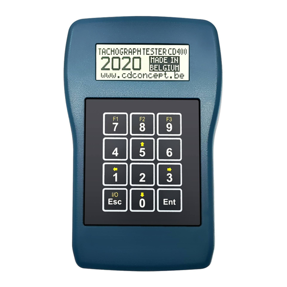
- Page 1 CD400 Tachograph programmer user manual CD400 V2.0 r07 b10 (2/10/2020)
- Page 2 Index: Introduction……………………. 3 4.1.4 Constant speed…………………15 What is a tachograph?..3 4.1.5 Draw-wire…………………………15 Description……………………... 3 4.1.6 Odometer…………………………16 Technical specifications…... 3 (only for digital tachographs. Keyboard………………………… 4 4.3 Parameters…………………………. 17 Connections……………………. 4 4.4 Speed test…………………………… 17 Operation………………………... 5 4.4.1 Manual……………………………. 17 Power supply and…………….
- Page 3 1. Introduction 1.1. What is a tachograph? Basically, a tachograph is a device that measures and records the speed and distance driven by a vehicle. The data are recorded in the form of graphics on a paper disk. The new digital tachographs record those data on its embedded memory and also on the smartcard of the driver.
- Page 4 2.2. Keyboard - Alternate function keys 'F1', 'F2' & 'F3' are active when a function in inverted video appears on the bottom line of the display. Trac k l eng th 0020m F1= MODIFY, F3=OK MODI FY - Alternate function key '↑' & '↓' are used for example to 1234 567 890 123 45 67 navigate the menus.
-
Page 5: Operation
3. Operation 3.1. Power supply and tachograph type detection For all tachograph types, except for the K13xx/1318 and the FTCO1319, the programmer is powered by the tachograph itself. An automatic tachograph type detection is executed on power ON, so don't switch the programmer ON, simply connect it to the tachograph with the appropriate cable. - Page 6 3.2.2. MTCO 1324/1390 M T CO 13 2 4 /1 3 9 0 1.M e asu r e W 1.M a nu al 2. P h ot o s e ns o r 2. P ar a m et er s 1.K F a ct o r 2.Od o m e te r 3.
- Page 7 3.2.3. Motometer EGK100 M o t o m et e r E GK 1 0 0 1.M e asu r e W 1.M a nu al 2. P h ot o s e ns o r 2. P ar a m et er s 1.K F a ct o r 2.K n 3.
- Page 8 3.2.4. Kienzle 1319 K i e nz l e 1 31 9 1.M e asu r e W 1.M a nu al 2. P h ot o s e ns o r 2.M e asu r e K 3. P ar a m et er s 1 .K f a ct o r 2 .Od o m et e r 3 .I ns t al .
- Page 9 3.2.5. V.Root VR2400 V. R o o t V R2 4 0 0 1.M e asu r e W 1.M a nu al 2. P h ot o s e ns o r 2. P ar a m et er s 1 .K f a ct o r 2 .Od o m et e r 3 .P ul se p e r r ev.
- Page 10 3.2.6. Digital VDO D IG ITA L V DO 1.M e asu r e W 1.M a nu al 2. P h ot o s e ns o r 2. P ar a m et er s 1.Calibration 1.W factor 2.K factor 3.L (Tyre Circ.) 4.Tyre Size...
- Page 11 7. Se n s or p a ir i ng 8. C l oc k t es t 9. PI N c o de 1 0.S e le c t T a ch o . 1 1. Pr od u ct i n f o. 1 2.L a ng u ag e .
- Page 12 4.Hardware number 5.Hardware vers. 6.Software number 7.Software vers. 8.License number 3. Sp eed te st 1.M a nu al 2.A u t o m at i c 4.Od o m e te r t es t 5. R ead DT C S 6.
- Page 13 4.Drv1 ign.ON 5.Drv2 ign.ON 6.Drv1 ign.OFF 7.Drv2 ign.OFF 8.Install. date 4.Information 1.Supplier Id 2.Manufact. Date 3.Serial number 4.Hardware number 5.Hardware vers. 6.Software number 7.Software vers. 8.License number 3. Sp eed te st 1.M a nu al 2.A u t o m at i c 4.Od o m e te r t es t 5.
- Page 14 3.2.8. Digital EFAS DIG I TA L EFA S 1.M e asu r e W 1.M a nu al 2. P h ot o s e ns o r 2. P ar a m et er s 1.Calibration 1.W factor 2.K factor 3.L (Tyre Circ.) 4.Tyre Size...
-
Page 15: Functions Description
3. Sp eed te st 1.M a nu al 2.A u t o m at i c 4.Od o m e te r t es t 5. R ead DT C S 6. E ra se DT C S 7. Se n s or p a ir i ng 8. - Page 16 K FA CT OR You can connect any photo sensor using a MiniDIN 4-pins connector connected to the left FACT ORT OP connector of the CD400. - Shielding: Ground (GND 0V). 1234 567 890 123 45 67 - Pin n°2: photo sensor signal (the signal should be low when the reference object/reflector is not detected).
- Page 17 CD400. Ente r d ist anc e: [ 503 ]cm As a result, the CD400 will display the K factor of the K: 5 546 p/ km tachograph, the W factor of the vehicle and the W: 5 512 p/ km Erro r: + 0 00.
- Page 18 4.2 Measure K This function is available only for the K1314/1318 and the FTCO 1319. Me asu re K 0020 p /km Measuring the K factor takes a few seconds. The value is updated every time the progress bar is completed. 4.3.
- Page 19 4.4.2 Automatic Select diagram Select the speed diagram to be executed and press 'Ent'. →1.Custom diag. 2.Tacho. 100km/h 3.Tacho. 125km/h 4.Tacho. 140km/h 5.Tacho. For the K1314/1318 the K reference is set to the last K measured if available, Cu sto m d iag . 160km/h otherwise it is set to 8000.
- Page 20 4.5. Odometer test The programmer will automatically simulate a speed of 50km/h on 1000m distance and check if the odometer as been incremented by 1000m. For the K1314/1318 the K reference is set to the last K measured if available, otherwise it is set to 8000. Od ome ter te st For the other tachographs the K reference is set to the K factor Kre f= 080 00 p/ km...
- Page 21 4.6. Read DTCs The function "Read DTCs" is used to read the "Diagnostic Trouble Codes" (DTC) stored in the error memory of the tachograph. It is available for the following tachographs: - Digital tachographs (DTCO1381, SE5000, SmarTach & EFAS) DTCs number is the error number available in memory DTCs number:03 Error code 01: 002452 (2F)
- Page 22 4.8. Sensor Pairing (Kitas activation) This function is available for the following tachographs: - MTCO 1324/1390 - VR2400 - Digital tachographs (DTCO1381, SE5000, SmarTach & EFAS) Sensor pairing is executed automatically after modifying any calibration parameter on digital tachographs. A progress bar indicates the status of KITAS activation.
- Page 23 4.10. PIN code The "PIN code" function permits to send the workshop card PIN code to the tachograph automatically. This function is available for the Digital tachographs (DTCO1381, SE5000 & EFAS) PIN code Select the workshop card ID in the list (ie: name of owner) and press 'Ent'. →...
- Page 24 5. Software upgrade procedure 1. Download and install the CD200-ISP software: setup-CD200-ISP-V1-2.zip 2. Connect the CD400 to the serial port of your PC using the upgrade cable (CA-RS232-1). 3. Start the CD200-ISP software. 4. Select the COM port. 5. Select the .hex file.
Need help?
Do you have a question about the CD400 and is the answer not in the manual?
Questions and answers