
Related Manuals for Hampshire Controls MPS

Summary of Contents for Hampshire Controls MPS
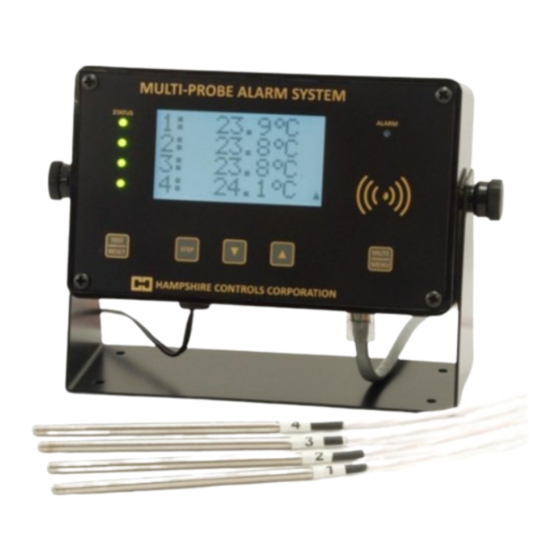
- Page 1 MULTI-PROBE ALARM SYSTEM OPERATING INSTRUCTIONS AMPSHIRE ONTROLS ORPORATION PO Box 516, Dover NH 03821 Tel (603) 749-9424 Toll-free (866) 496-9424 Fax (603) 749-9433 www.hampshirecontrols.com...
-
Page 2: Limited Warranty
Products believed to have such defects must be returned to the factory by prepaid transportation. Hampshire Controls’ obligation under this warranty is limited to the repair or replacement, at its option, of those items which upon examination prove to be defective. Such repair or replacement will be made without charge. -
Page 3: Table Of Contents
Power Loss ..........................14 Sensor Limits..........................14 Door Switch Alarm ........................14 Alarm Relay Testing ......................... 15 MPS Email Notification Feature ....................15 Email Server Requirements ....................... 15 Email Notification Configuration....................16 Testing Email Transmission ...................... 18 20 Mar. 2021... -
Page 4: Multi-Probe Alarm System Components
Hampshire Controls Corporation Multi-Probe Alarm System Components 20 Mar. 2021 MPS Operating Manual Page 3... - Page 5 Probe channels 5 to 8 (MPS-8) b. NO/NC (Form-C) relay connections (MPS-2/3/4 with more than one relay) 12. Four 3-pin pluggable terminal blocks (MPS-2/3/4 with voltage or current output) 13. One 2-pin pluggable terminal block a. Switch input (MPS-2/3/4 with more than one relay) b.
-
Page 6: Sensor Probe
The probes will be pre-wired to terminal-block plugs which mate with the pluggable terminal- block sockets on the back of the MPS. Each connection will be marked with identifying information about the probe or relay connection and any other pertinent electrical information. -
Page 7: Probe Location
During shipping, this circuit prevents the battery from supplying power to the MPS. When you plug in the MPS power supply for the first the time, the circuit will activate, preventing the device from turning off when power is disconnected. -
Page 8: Sensor Readings Display
Hampshire Controls Corporation If the MPS turns back on (in a PowerFail state) you will need to repeat the procedure by first plugging in the power supply. Then, be sure to HOLD DOWN the TEST/RESET button during the entire procedure. You may also increase the time you keep the button held down after unplugging the power supply. -
Page 9: Alarm Limits And Min/Max Readings
While in the Edit Limits menu, the STEP button will advance through Low and High limits for each probe. Continue to the Edit Times menu by pressing the MUTE/MENU button once, or return to the sensor readings by pressing the MUTE/MENU button twice. 20 Mar. 2021 MPS Operating Manual Page 8... -
Page 10: Setting Alarm Delays
Door Input, tap the STEP button. For units that have multiple probe inputs configured as dry-contact switch inputs, the normal probe configuration parameters are used to configure the alarms and delays. 20 Mar. 2021 MPS Operating Manual Page 9... -
Page 11: Configuration Parameter Descriptions
(periodic chirp only) until either the alarm condition goes away, or the mute time elapses. The range is 0 to 120, with a default of 15. 20 Mar. 2021 MPS Operating Manual Page 10... - Page 12 MPS on site. The range is 1 to 999, with a default of 1. IP1, IP2, IP3, and IP4 The IP parameters define the four octets of the static IP address for the MPS. The default values are 192, 168, 0, and 141 respectively.
- Page 13 Netmask1, Netmask2, Netmask3, and Netmask4 These parameters define the four octets of the subnet mask for the MPS. The default values are 255, 255, 255, and 0 respectively. They are only available as parameters on MPS units configured to work with our ALERT Monitoring System. For other units, this value is specified in the configured web page (http://192.168.0.141/setup.html).
-
Page 14: Configuration Parameter Flowchart
Hampshire Controls Corporation Configuration Parameter Flowchart 20 Mar. 2021 MPS Operating Manual Page 13... -
Page 15: Alarms
Alarms Power Loss When the MPS loses line-power it will continue to operate on the internal LiPo battery. However, the following changes in operation will occur: Display and backlight will turn off to save power (press any button to enable) ... -
Page 16: Alarm Relay Testing
15 seconds. MPS Email Notification Feature A standard feature of the MPS is the ability to send temperature alarm notifications and daily temperature reports via email. The MPS sends email on: ... -
Page 17: Email Notification Configuration
MPS. To do this, you will first need to connect a computer with a 10/100/1000 base-T network adapter to the MPS using a standard Ethernet patch cable. Configure the computer’s Ethernet adapter with a static IP of 192.168.0.140 and subnet mask of 255.255.255.0. - Page 18 IP address in the Edit*SETUP* menu, and reset the MPS (press-and-hold the TEST/RESET button until the backlight and LEDs turn off), prior to attempting to connect to the web pages again using the newly assigned IP address from computers on your local network.
-
Page 19: Testing Email Transmission
Hampshire Controls Corporation Testing Email Transmission On the main MPS web page (http://[IP address of MPS]) click the “Send test email (to all)” hyperlink and wait (up to 2 minutes, depending if the SMTP connection is successful or times out).
Need help?
Do you have a question about the MPS and is the answer not in the manual?
Questions and answers