
Related Manuals for heinzinger ERS Compact Series


Summary of Contents for heinzinger ERS Compact Series
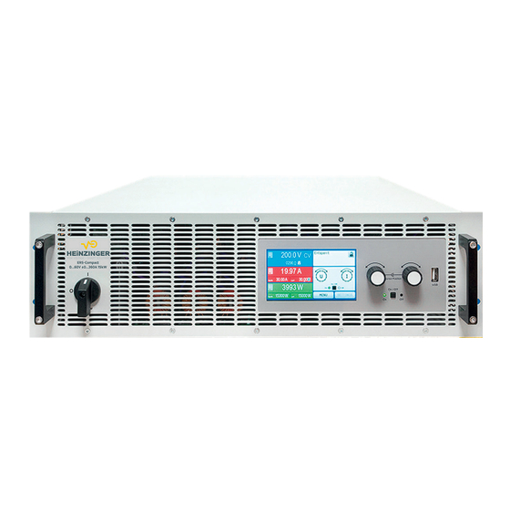
- Page 1 Betriebsanleitung User Manual Bidirectional Power Supply System Heinzinger ERS Compact-Series www.heinzinger.com...
-
Page 2: Table Of Contents
TABLE OF CONTENTS . GENERAL About this document ........5 2.3.2 Preparation ...........36 1.1.1 Retention and use ..........5 2.3.3 Installing the device ........39 2.3.4 Connection to water supply (WC models) ..40 1.1.2 Copyright ............5 1.1.3 Validity ............5 2.3.5 Connection to AC supply ......42 1.1.4 Symbols and warnings ........5 2.3.6 Connection to DC loads or DC sources ..45 Warranty ............5... - Page 3 3.5.9 The quick menu ...........66 3.5.10 The graph .............67 Remote control ..........68 3.6.1 General ............68 3.6.2 Control locations ..........68 3.6.3 Remote control via a digital interface ..68 3.6.4 Remote control via the analog interface ..71 Alarms and monitoring .........76 3.7.1 Definition of terms ........76 3.7.2 Device alarm and event handling ....76 3.8...
- Page 4 ERS COMPACT Heinzinger electronic GmbH Phone: +49 (0) 8031 2458 0 www.heinzinger.com Anton-Jakob-Str. 4, 83026 Rosenheim Fax: + 49 (0) 8031 2458 58 info@heinzinger.de Page 4 Germany...
-
Page 5: About This Document
Symbol for general safety notices (instructions and damage protection bans) or important infor- mation for operation Symbol for general notices Warranty Heinzinger guarantees the functional competence of the applied technology and the stated performance param- eters. The warranty period begins with the delivery of free from defects equipment. Terms of guarantee are included in the general terms and conditions (TOS) of Heinzinger. Limitation of liability All statements and instructions in this manual are based on current norms and regulations, up-to-date technology and our long term knowledge and experience. -
Page 6: Disposal Of Equipment
• Claims of any sort due to damage caused by non-intended usage will not be accepted • All damage caused by non-intended usage is solely the responsibility of the operator Heinzinger electronic GmbH Phone: +49 (0) 8031 2458 0 www.heinzinger.com Anton-Jakob-Str. -
Page 7: Safety
• It’s not allowed to run the device on AC sources such as generators or UPS equipment. It must only be connected to a power grid! Heinzinger electronic GmbH Phone: +49 (0) 8031 2458 0 www.heinzinger.com Anton-Jakob-Str. 4, 83026 Rosenheim Fax: + 49 (0) 8031 2458 58 info@heinzinger.de... -
Page 8: Responsibility Of The User
Delegated persons are those who have been properly and demonstrably instructed in their tasks and the atten- dant dangers. Qualified persons are those who are able through training, knowledge and experience as well as knowledge of the specific details to carry out all the required tasks, identify dangers and avoid personal and other risks. All work on electrical equipment may only be performed by qualified electricians. Heinzinger electronic GmbH Phone: +49 (0) 8031 2458 0 www.heinzinger.com Anton-Jakob-Str. 4, 83026 Rosenheim Fax: + 49 (0) 8031 2458 58 info@heinzinger.de... -
Page 9: Alarm Signals
The rated values for the device determine the maximum adjustable ranges. 1.8.2.1 Terms In connection with the model of any of the devices mentioned below, the word “standard” or “standard model” refers to the basic version with display, which also applies to the versions with water cooling or US208V option, as they don’t change the manual handling on the HMI. Heinzinger electronic GmbH Phone: +49 (0) 8031 2458 0 www.heinzinger.com Anton-Jakob-Str. 4, 83026 Rosenheim Fax: + 49 (0) 8031 2458 58 info@heinzinger.de... -
Page 10: Specific Technical Data (380/400/480 V Models)
Current regulation (el. load) Load regulation at 0...100% ΔU ≤ 0.15% I ≤ 0.15% I ≤ 0.15% I ≤ 240 mA ≤ 240 mA ≤ 66 mA Ripple (1 Related to the nominal values, the accuracy defines the maximum deviation between an adjusted values and the true (actual) value. Example: a 1000 A model has min. 0.2% current accuracy, that is 2 A. When adjusting the current to 300 A, the actual current on the DC terminal is allowed to differ max. 2 A from the set value, which means it could be between 298 A and 302 A. (2 RMS value: LF 0...300 kHz, PP value: HF 0...20MHz (3 The display error adds to the error of the related actual value on the DC terminal Heinzinger electronic GmbH Phone: +49 (0) 8031 2458 0 www.heinzinger.com Anton-Jakob-Str. 4, 83026 Rosenheim Fax: + 49 (0) 8031 2458 58 info@heinzinger.de Page 10 Germany... - Page 11 (2 The display error adds to the error of the related actual value on the DC terminal (3 For technical specifications of the analog interface see “3.6.4.5 Analog interface specification” on page 72 (4 Typical value at 100% voltage and 100% power (5 WC = with optional water-cooling Heinzinger electronic GmbH Phone: +49 (0) 8031 2458 0 www.heinzinger.com Anton-Jakob-Str. 4, 83026 Rosenheim Fax: + 49 (0) 8031 2458 58 info@heinzinger.de...
- Page 12 Current regulation (el. load) Load regulation at 0...100% ΔU ≤ 0.15% I ≤ 0.15% I ≤ 0.15% I ≤ 50 mA ≤ 48 mA ≤ 48 mA Ripple (1 Related to the nominal values, the accuracy defines the maximum deviation between an adjusted values and the true (actual) value. Example: a 1000 A model has min. 0.2% current accuracy, that is 2 A. When adjusting the current to 300 A, the actual current on the DC terminal is allowed to differ max. 2 A from the set value, which means it could be between 298 A and 302 A. (2 RMS value: LF 0...300 kHz, PP value: HF 0...20MHz (3 The display error adds to the error of the related actual value on the DC terminal Heinzinger electronic GmbH Phone: +49 (0) 8031 2458 0 www.heinzinger.com Anton-Jakob-Str. 4, 83026 Rosenheim Fax: + 49 (0) 8031 2458 58 info@heinzinger.de Page 12 Germany...
- Page 13 (2 The display error adds to the error of the related actual value on the DC terminal (3 For technical specifications of the analog interface see “3.6.4.5 Analog interface specification” on page 72 (4 Typical value at 100% voltage and 100% power (5 WC = with optional water-cooling Heinzinger electronic GmbH Phone: +49 (0) 8031 2458 0 www.heinzinger.com Anton-Jakob-Str. 4, 83026 Rosenheim Fax: + 49 (0) 8031 2458 58 info@heinzinger.de...
- Page 14 Current regulation (el. load) Load regulation at 0...100% ΔU ≤ 0.15% I ≤ 0.15% I ≤ 0.15% I ≤ 16 mA ≤ 26 mA ≤ 26 mA Ripple (1 Related to the nominal values, the accuracy defines the maximum deviation between an adjusted values and the true (actual) value. Example: a 1000 A model has min. 0.2% current accuracy, that is 2 A. When adjusting the current to 300 A, the actual current on the DC terminal is allowed to differ max. 2 A from the set value, which means it could be between 298 A and 302 A. (2 RMS value: LF 0...300 kHz, PP value: HF 0...20MHz (3 The display error adds to the error of the related actual value on the DC terminal Heinzinger electronic GmbH Phone: +49 (0) 8031 2458 0 www.heinzinger.com Anton-Jakob-Str. 4, 83026 Rosenheim Fax: + 49 (0) 8031 2458 58 info@heinzinger.de Page 14 Germany...
- Page 15 (2 The display error adds to the error of the related actual value on the DC terminal (3 For technical specifications of the analog interface see “3.6.4.5 Analog interface specification” on page 72 (4 Typical value at 100% voltage and 100% power (5 WC = with optional water-cooling Heinzinger electronic GmbH Phone: +49 (0) 8031 2458 0 www.heinzinger.com Anton-Jakob-Str. 4, 83026 Rosenheim Fax: + 49 (0) 8031 2458 58 info@heinzinger.de...
-
Page 16: Specific Technical Data (208 V Models)
15000 W 15000 W 0...16500 W 0...16500 W 0...16500 W Overpower protection Power regulation 0...15300 W 0...15300 W 0...15300 W Adjustment range (1 WC = water cooling option installed Heinzinger electronic GmbH Phone: +49 (0) 8031 2458 0 www.heinzinger.com Anton-Jakob-Str. 4, 83026 Rosenheim Fax: + 49 (0) 8031 2458 58 info@heinzinger.de Page 16 Germany... -
Page 17: Views
ERS COMPACT 1.8.5 Views Heinzinger electronic GmbH Phone: +49 (0) 8031 2458 0 www.heinzinger.com Anton-Jakob-Str. 4, 83026 Rosenheim Fax: + 49 (0) 8031 2458 58 info@heinzinger.de Page 17 Germany... - Page 18 ERS COMPACT Heinzinger electronic GmbH Phone: +49 (0) 8031 2458 0 www.heinzinger.com Anton-Jakob-Str. 4, 83026 Rosenheim Fax: + 49 (0) 8031 2458 58 info@heinzinger.de Page 18 Germany...
- Page 19 ERS COMPACT Heinzinger electronic GmbH Phone: +49 (0) 8031 2458 0 www.heinzinger.com Anton-Jakob-Str. 4, 83026 Rosenheim Fax: + 49 (0) 8031 2458 58 info@heinzinger.de Page 19 Germany...
- Page 20 ERS COMPACT Heinzinger electronic GmbH Phone: +49 (0) 8031 2458 0 www.heinzinger.com Anton-Jakob-Str. 4, 83026 Rosenheim Fax: + 49 (0) 8031 2458 58 info@heinzinger.de Page 20 Germany...
- Page 21 ERS COMPACT Heinzinger electronic GmbH Phone: +49 (0) 8031 2458 0 www.heinzinger.com Anton-Jakob-Str. 4, 83026 Rosenheim Fax: + 49 (0) 8031 2458 58 info@heinzinger.de Page 21 Germany...
- Page 22 ERS COMPACT Heinzinger electronic GmbH Phone: +49 (0) 8031 2458 0 www.heinzinger.com Anton-Jakob-Str. 4, 83026 Rosenheim Fax: + 49 (0) 8031 2458 58 info@heinzinger.de Page 22 Germany...
- Page 23 ERS COMPACT Heinzinger electronic GmbH Phone: +49 (0) 8031 2458 0 www.heinzinger.com Anton-Jakob-Str. 4, 83026 Rosenheim Fax: + 49 (0) 8031 2458 58 info@heinzinger.de Page 23 Germany...
- Page 24 ERS COMPACT Figure 8 - Top view (example of a standard model with DC terminal type 1 and water cooling option) Heinzinger electronic GmbH Phone: +49 (0) 8031 2458 0 www.heinzinger.com Anton-Jakob-Str. 4, 83026 Rosenheim Fax: + 49 (0) 8031 2458 58 info@heinzinger.de Page 24 Germany...
-
Page 25: Control Elements (Standard Models)
Used to toggle the DC terminal between on and off, also used to start a function run. The LEDs “On” and “Off” indicate the state of the DC terminal, no matter if the device is manually controlled or remotely. Port for USB sticks For the connection of standard USB sticks. See section “1.9.6.5. USB port (front side)” for more details. Heinzinger electronic GmbH Phone: +49 (0) 8031 2458 0 www.heinzinger.com Anton-Jakob-Str. 4, 83026 Rosenheim Fax: + 49 (0) 8031 2458 58 info@heinzinger.de... -
Page 26: Control Elements (Slave Models)
This port has reduced functionality compared to the rear port. Status indicators (LED) These six colour LEDs show the device status. For details refer to 1.9.7.1. Heinzinger electronic GmbH Phone: +49 (0) 8031 2458 0 www.heinzinger.com Anton-Jakob-Str. 4, 83026 Rosenheim Fax: + 49 (0) 8031 2458 58 info@heinzinger.de... -
Page 27: Construction And Function
Power block Controller (DR) ≈ ≈ Commu- Commu- nication nication (KE) (KE) PSB 10000 Block diagram Heinzinger electronic GmbH Phone: +49 (0) 8031 2458 0 www.heinzinger.com Anton-Jakob-Str. 4, 83026 Rosenheim Fax: + 49 (0) 8031 2458 58 info@heinzinger.de Page 27 Germany... -
Page 28: Scope Of Delivery
ENS2 Single ELR/ERSC/ERSCE up to ENS2 10,5kW yes, 2 / 10,5 kW 10.5kW Single ELR/ERSC/ERSCE up to ENS2 30kW yes, 2 / 30 kW 30kW Heinzinger electronic GmbH Phone: +49 (0) 8031 2458 0 www.heinzinger.com Anton-Jakob-Str. 4, 83026 Rosenheim Fax: + 49 (0) 8031 2458 58 info@heinzinger.de Page 28 Germany... -
Page 29: Options
The set values can be adjusted with the rotary knobs next to the display screen or can be entered directly via the touchscreen. When adjusting with the knobs, pushing the knob will select the digit to be changed. Logically, the values are increased by clockwise turning and decreased by anti-clockwise turning. Heinzinger electronic GmbH Phone: +49 (0) 8031 2458 0 www.heinzinger.com Anton-Jakob-Str. - Page 30 (only with R mode active) Due to the device having two set values each for current, power and resistance, tapping multiple times will cycle through the 4 resp. 6 assignable set values for this knob. The currently not selected set values can’t be adjusted via the rotary knob, unless the assignment is changed. Heinzinger electronic GmbH Phone: +49 (0) 8031 2458 0 www.heinzinger.com Anton-Jakob-Str. 4, 83026 Rosenheim Fax: + 49 (0) 8031 2458 58 info@heinzinger.de...
- Page 31 The name must begin with ERSC_pv or ERSC_fc, the rest can 3.11.14 be user defined. pv_day_et_<arbitrary_text>.csv Day trend data file to load for the simulation modes DAY I/T and 3.11.15.5 pv_day_ui_<arbitrary_text>.csv DAY U/I of the extended PV function. Heinzinger electronic GmbH Phone: +49 (0) 8031 2458 0 www.heinzinger.com Anton-Jakob-Str. 4, 83026 Rosenheim Fax: + 49 (0) 8031 2458 58 info@heinzinger.de Page 31 Germany...
-
Page 32: The Control Panel (Slave Models)
“3.7. Alarms and monitoring”. Constant current regulation (CC) is active. It means, if the LED isn’t lit it indicates yellow either CV, CP or CR mode. Also see “3.3. Operating modes”. green DC terminal is switched on DC terminal is switched off Heinzinger electronic GmbH Phone: +49 (0) 8031 2458 0 www.heinzinger.com Anton-Jakob-Str. 4, 83026 Rosenheim Fax: + 49 (0) 8031 2458 58 info@heinzinger.de Page 32... -
Page 33: Usb Port (Rear Side)
CAN 2.0 A / 2.0 B, 1x DB9, male IF-AB-CAN EtherCAT, 1x RJ45 IF-AB-ECT The modules can be installed by the user and hence retrofitted without problem. A firmware update of the device may be necessary in order to recognize and support certain modules. Heinzinger electronic GmbH Phone: +49 (0) 8031 2458 0 www.heinzinger.com Anton-Jakob-Str. 4, 83026 Rosenheim Fax: + 49 (0) 8031 2458 58 info@heinzinger.de Page 33... -
Page 34: Analog Interface (Standard Models)
It’s recommended to keep the connections as short as possible and to terminate the bus if required. The termination is done via digital switches and activated in the device setup menu in group “Master-Slave”. Heinzinger electronic GmbH Phone: +49 (0) 8031 2458 0 www.heinzinger.com Anton-Jakob-Str. 4, 83026 Rosenheim Fax: + 49 (0) 8031 2458 58 info@heinzinger.de... -
Page 35: Ethernet Port (Standard Models)
• No direct dissipation of heat into the ambiance of the device However, there also disadvantages: • The device isn’t allowed to run under load without active water flow • Water flow inside an electronic device includes a higher risk of damage caused by a leak or by condensation of water from air humidity (dewing) The water taps are located on the rear side of the device, also see the rear view drawing in section 1.8.5. Details about the connection, requirements and use of the water cooling can be found in section 2.3.4. Heinzinger electronic GmbH Phone: +49 (0) 8031 2458 0 www.heinzinger.com Anton-Jakob-Str. 4, 83026 Rosenheim Fax: + 49 (0) 8031 2458 58 info@heinzinger.de Page 35... -
Page 36: Installation & Commissioning
2.3.2 Preparation 2.3.2.1 Planning a master-slave system In case a master-slave system is planned, it should prior to any installation and wiring be decided how the mas- ter-slave system shall be configured. The smallest setup would consist of 2x ERSC 10000 or 1x ERSC 10000 and 1x ERSC 10000 Slave. Both, master and slave unit, must be of same rating regarding voltage, current and power. The device must also be of the same type, in this case bidirectional. This means, it would also allow for paralleling with ERSCE 10000 series. Heinzinger electronic GmbH Phone: +49 (0) 8031 2458 0 www.heinzinger.com Anton-Jakob-Str. 4, 83026 Rosenheim Fax: + 49 (0) 8031 2458 58 info@heinzinger.de Page 36 Germany... - Page 37 Disadvantage of this combination: higher costs, because even some of the slave units may have a display and control panel which they actually don’t need. Heinzinger electronic GmbH Phone: +49 (0) 8031 2458 0 www.heinzinger.com Anton-Jakob-Str. 4, 83026 Rosenheim Fax: + 49 (0) 8031 2458 58 info@heinzinger.de...
- Page 38 Accessories” and “2.3.5.3. Restriction when operating the device with NS protection”.Concept of an NS protection system: GRID Supervision Device Heinzinger electronic GmbH Phone: +49 (0) 8031 2458 0 www.heinzinger.com Anton-Jakob-Str. 4, 83026 Rosenheim Fax: + 49 (0) 8031 2458 58 info@heinzinger.de...
-
Page 39: Installing The Device
The unacceptable positions, as shown below, are also valid for the vertical mount of the device onto a wall or inside a cabinet. The required air flow would be insufficient. This wouldn’t actually apply to water cooled models, but the construction of the entire device isn’t made for operation in this position. Acceptable and unacceptable installation positions (air or water cooled, air cooled shown): Standing surface Heinzinger electronic GmbH Phone: +49 (0) 8031 2458 0 www.heinzinger.com Anton-Jakob-Str. 4, 83026 Rosenheim Fax: + 49 (0) 8031 2458 58 info@heinzinger.de... -
Page 40: Connection To Water Supply (Wc Models)
26.21 27.26 28.18 29.09 30°C 16.79 18.44 19.96 21.44 23.71 23.94 25.11 26.1 27.21 28.19 Heinzinger electronic GmbH Phone: +49 (0) 8031 2458 0 www.heinzinger.com Anton-Jakob-Str. 4, 83026 Rosenheim Fax: + 49 (0) 8031 2458 58 info@heinzinger.de Page 40 Germany... - Page 41 111.3 101.3 104.2 106.9 109.4 120.2 122°F 94.6 111.8 116.2 118.3 2.3.4.4 Notes • The water flow should be started prior to powering the device, but at least prior to switching the DC terminal on Heinzinger electronic GmbH Phone: +49 (0) 8031 2458 0 www.heinzinger.com Anton-Jakob-Str. 4, 83026 Rosenheim Fax: + 49 (0) 8031 2458 58 info@heinzinger.de Page 41 Germany...
-
Page 42: Connection To Ac Supply
Therefore the mains cable should be kept as short as possible or have an even bigger cross section. Cables with 4 or 5 conductors can be used. When using a cable with N conductor, it’s allowed to clamp it into the spare pin of the AC plug. Figure 11 - Example for an AC cable with 4 conductors (european color code, cable not included in delivery) Heinzinger electronic GmbH Phone: +49 (0) 8031 2458 0 www.heinzinger.com Anton-Jakob-Str. 4, 83026 Rosenheim Fax: + 49 (0) 8031 2458 58 info@heinzinger.de... - Page 43 AWG 8 The included connection plug can receive lose/soldered cable ends of up to 16 mm² (AWG 6). The longer the connection cable, the higher the voltage loss due to the cable resistance. Therefore the mains cables should be kept as short as possible or use bigger cross section. Connection scheme: Figure 13 - Example for an AC cable with 4 conductors (US color code, cable not included in delivery) Heinzinger electronic GmbH Phone: +49 (0) 8031 2458 0 www.heinzinger.com Anton-Jakob-Str. 4, 83026 Rosenheim Fax: + 49 (0) 8031 2458 58 info@heinzinger.de...
- Page 44 Consumer 1 PSB(E) 10000 Consumer 2 Consumer 2 When running a higher number of recovering, i. e. energy backfeeding units on the same leg of the installation, the total currents per phase increases accordingly. Heinzinger electronic GmbH Phone: +49 (0) 8031 2458 0 www.heinzinger.com Anton-Jakob-Str. 4, 83026 Rosenheim Fax: + 49 (0) 8031 2458 58 info@heinzinger.de Page 44...
-
Page 45: Connection To Dc Loads Or Dc Sources
The connection angle and the required bending radius for the DC cable must be taken into account when planning the depth of the complete device, especially when installing in a 19” cabinet or similar installations. Heinzinger electronic GmbH Phone: +49 (0) 8031 2458 0 www.heinzinger.com Anton-Jakob-Str. -
Page 46: Connection Of Remote Sensing
• In master-slave operation, the remote sensing should be connected to the master unit only • The dielectric strength of the sense wires must always at least match the DC voltage rating! Figure 14 - Example for remote sensing wiring with a load and operation in source mode (sink mode would be wired identically, with a source) Allowed connection schemes: Heinzinger electronic GmbH Phone: +49 (0) 8031 2458 0 www.heinzinger.com Anton-Jakob-Str. 4, 83026 Rosenheim Fax: + 49 (0) 8031 2458 58 info@heinzinger.de... -
Page 47: Grounding Of The Dc Terminal
2.3.10 Connection of the analog interface The 15 pole connector (type: D-sub, VGA) on the rear side is an analog interface. To connect this to a controlling hardware (PC, electronic circuit), a standard plug is necessary (not included in the scope of delivery). It’s generally advisable to switch the device completely off before connecting or disconnecting this connector, but at least the DC terminal. Heinzinger electronic GmbH Phone: +49 (0) 8031 2458 0 www.heinzinger.com Anton-Jakob-Str. 4, 83026 Rosenheim Fax: + 49 (0) 8031 2458 58 info@heinzinger.de Page 47... -
Page 48: Connection Of The Share Bus
Refer to “2.3.13. Initial commission”. Only after successful checking of the device as listed may it be operated as usual. Heinzinger electronic GmbH Phone: +49 (0) 8031 2458 0 www.heinzinger.com Anton-Jakob-Str. -
Page 49: Terms
Transient time after load step (source mode) 3.3.1.1 For constant voltage mode (CV), the technical date “Transient time after load step” (see 1.8.3) defines a time that is required by the internal voltage regulator of the device to settle the voltage (in source mode) after a load step. Negative load steps, i.e. high load to lower load, will cause the output voltage to overshoot for a short time until compensated by the voltage regulator. Heinzinger electronic GmbH Phone: +49 (0) 8031 2458 0 www.heinzinger.com Anton-Jakob-Str. 4, 83026 Rosenheim Fax: + 49 (0) 8031 2458 58 info@heinzinger.de Page 49... -
Page 50: Current Regulation / Constant Current / Current Limiting
While the DC power stage is switched on and constant power mode is active, the condition “CP mode active” will be indicated on the graphics display by the abbre- viation CP, as well stored as status which can also be read as a status message via digital interface. Heinzinger electronic GmbH Phone: +49 (0) 8031 2458 0 www.heinzinger.com Anton-Jakob-Str. 4, 83026 Rosenheim Fax: + 49 (0) 8031 2458 58 info@heinzinger.de... -
Page 51: Internal Resistance Regulation (Source Mode)
CV and CR. It’s thus not advised to adjust the voltage set value to the same level as the external source. The internal resistance is naturally limited between almost zero and maximum, where the resolution of current regulation becomes very inaccurate. Because the internal resistance can’t have a value of zero, the lower limit is defined to an achievable minimum. This ensures that the internal electronic load, at very low input voltages, can consume a high input current from the source, up to the adjusted current set value. While the DC input is switched on and constant resistance mode is active, the condition “CR mode active” will be indicated on the graphics display by the abbreviation CR, as well it will be stored as internal status that can be read via digital interface. Heinzinger electronic GmbH Phone: +49 (0) 8031 2458 0 www.heinzinger.com Anton-Jakob-Str. 4, 83026 Rosenheim Fax: + 49 (0) 8031 2458 58 info@heinzinger.de Page 51 Germany... -
Page 52: Sink-Source Mode Switching
The instability is not caused by a malfunction of the load, but by the behavior of the complete system. An improve- ment of the phase and gain margin can solve this. In practice, a capacity is directly connected to the DC input, perhaps alternatively to the remote sense input, if connected to the source. The value to achieve the expected result is not defined and has to be found out. We recommend: 60/80 V models: 1000uF..4700uF 200/360 V models: 100uF...470uF 500 V models: 47uF...150uF 750/1000 V models: 22uF...100uF 1500/2000 V models: 4.7uF...22uF Heinzinger electronic GmbH Phone: +49 (0) 8031 2458 0 www.heinzinger.com Anton-Jakob-Str. 4, 83026 Rosenheim Fax: + 49 (0) 8031 2458 58 info@heinzinger.de Page 52 Germany... -
Page 53: Alarm Conditions
• the product of the voltage and current in the DC terminal reaches the adjusted OPP limit. This function serves to protect the connected load application (source mode) or the external source (sink mode) so it’s not overloaded and possibly damaged due to an excessive power. Heinzinger electronic GmbH Phone: +49 (0) 8031 2458 0 www.heinzinger.com Anton-Jakob-Str. -
Page 54: Safety Ovp
• a short-circuit on the Share bus has occurred, for example due to a damaged BNC cable. This function serves to prevent sending irregular control signals to the slave units via the Share bus or to cause them to react differently. This alarm has to be acknowledged after the cause has been removed. Heinzinger electronic GmbH Phone: +49 (0) 8031 2458 0 www.heinzinger.com Anton-Jakob-Str. 4, 83026 Rosenheim Fax: + 49 (0) 8031 2458 58 info@heinzinger.de... -
Page 55: Manual Operation
Many settings are self-explanatory, others are not. Those will be explained on the pages following. Heinzinger electronic GmbH Phone: +49 (0) 8031 2458 0 www.heinzinger.com Anton-Jakob-Str. 4, 83026 Rosenheim Fax: + 49 (0) 8031 2458 58 info@heinzinger.de... - Page 56 Pin 6 of the analog interface (see section 3.6.4.5) is by default assigned to signal both device alarms OT and PF. This parameter allows to also enable signaling only one of both (3 possible combinations): • Alarm OT = Signals only alarm OT • Alarm PF = Signals only alarm PF • Alarm PF + OT = Default, signals either PF or OT Heinzinger electronic GmbH Phone: +49 (0) 8031 2458 0 www.heinzinger.com Anton-Jakob-Str. 4, 83026 Rosenheim Fax: + 49 (0) 8031 2458 58 info@heinzinger.de Page 56 Germany...
- Page 57 Determines the condition of the DC terminal after leaving remote control either manually or by command: • Off = Default, DC terminal will always be off after leaving remote control • Auto = DC terminal will keep the last state Heinzinger electronic GmbH Phone: +49 (0) 8031 2458 0 www.heinzinger.com Anton-Jakob-Str. 4, 83026 Rosenheim Fax: + 49 (0) 8031 2458 58 info@heinzinger.de...
- Page 58 Defines the time between two records in the log file. Selection: 500 Start/stop Defines how the USB logging is started and stopped. Manual = Logging only starts and stops upon user interaction on the HMI, by accessing touch button in the quick menu. At DC on/off = Logging starts and stops with every change of state on the DC terminal, no matter if caused by the user, software or a device alarm. Attention: Every next start will create a new log file. Heinzinger electronic GmbH Phone: +49 (0) 8031 2458 0 www.heinzinger.com Anton-Jakob-Str. 4, 83026 Rosenheim Fax: + 49 (0) 8031 2458 58 info@heinzinger.de Page 58 Germany...
- Page 59 10 kbps, 20 kbps, 50 kbps, 100 kbps, 125 kbps, 250 kbps, 500 kbps, 800 kbps, 1Mbps Node Address Selection of the CANopen node address in the range 1...127 Heinzinger electronic GmbH Phone: +49 (0) 8031 2458 0 www.heinzinger.com Anton-Jakob-Str. 4, 83026 Rosenheim Fax: + 49 (0) 8031 2458 58 info@heinzinger.de...
- Page 60 Location Tag tag. Max. length: 22 characters String input box for a user-definable text which describes the Profibus slave instal- Installation Date lation date tag. Max. length: 40 characters String input box for a user-definable text which describes the Profibus slave. Max. Description length: 54 characters String input box for a user-definable text which describes the Profinet station name. Station Name Max. length: 200 characters Heinzinger electronic GmbH Phone: +49 (0) 8031 2458 0 www.heinzinger.com Anton-Jakob-Str. 4, 83026 Rosenheim Fax: + 49 (0) 8031 2458 58 info@heinzinger.de Page 60 Germany...
- Page 61 Module firmware CAN module firmware version IF Settings Description The baud rate is selectable, other serial settings can’t be changed and are Baud rate defined like this: 8 data bits, 1 stop bit, parity = none Baud rates: 2400Bd, 4800Bd, 9600Bd, 19200Bd, 38400Bd, 57600Bd, 115200Bd Heinzinger electronic GmbH Phone: +49 (0) 8031 2458 0 www.heinzinger.com Anton-Jakob-Str. 4, 83026 Rosenheim Fax: + 49 (0) 8031 2458 58 info@heinzinger.de Page 61 Germany...
- Page 62 The choice here is whether the backlight remains permanently on (default) or if it should go off when no input via screen or rotary knob is done for 60 s. As soon as there is input, the backlight returns automatically. Furthermore, the backlight intensity can be adjusted here. See ““3.8. Locking the control panel (HMI)” and “3.9. Locking the “Limits” and “Profiles”” Lock Heinzinger electronic GmbH Phone: +49 (0) 8031 2458 0 www.heinzinger.com Anton-Jakob-Str. 4, 83026 Rosenheim Fax: + 49 (0) 8031 2458 58 info@heinzinger.de...
-
Page 63: Adjustment Limits
See section 3.5.6. The actual operating mode, which is only indicated while the DC terminal is switched on, solely depends only on the set values. For more information see section “3.3. Operating modes”. Heinzinger electronic GmbH Phone: +49 (0) 8031 2458 0 www.heinzinger.com Anton-Jakob-Str. 4, 83026 Rosenheim Fax: + 49 (0) 8031 2458 58 info@heinzinger.de... -
Page 64: Manual Adjustment Of Set Values (Standard Models)
DC terminal. Upon entering a value which exceeds the corresponding limit, a note would pop up, the value in the frame reset to 0 and not be accepted and submitted. Heinzinger electronic GmbH Phone: +49 (0) 8031 2458 0 www.heinzinger.com Anton-Jakob-Str. -
Page 65: Switching The Dc Terminal On Or Off
Soon after logging has been started, the symbol indicates the ongoing logging action. In case there is an error while logging, such as the USB stick is full or removed, it will be indicated by another symbol ( ). After every manual stop or switching the DC terminal off the logging is stopped and the log file closed. Heinzinger electronic GmbH Phone: +49 (0) 8031 2458 0 www.heinzinger.com Anton-Jakob-Str. 4, 83026 Rosenheim Fax: + 49 (0) 8031 2458 58 info@heinzinger.de... -
Page 66: The Quick Menu
OT or PF 3.5.9 The quick menu The device offers a quick menu which allows for the quick access to often used features and modes being switched on or off in the “Settings” menu. It can be opened by swiping up from the bottom screen edge or tapping the bar: Overview: Heinzinger electronic GmbH Phone: +49 (0) 8031 2458 0 www.heinzinger.com Anton-Jakob-Str. 4, 83026 Rosenheim Fax: + 49 (0) 8031 2458 58 info@heinzinger.de... -
Page 67: The Graph
• Tapping the sides (arrows left/right) of the red/green/blue touch areas increases/decreases the vertical scaling • Tapping the sides (arrows left/right) of the black touch area increases/decreases the horizontal scaling • Swiping on the three scales (Y axis) moves them up or down • Tapping the menu touch area ( ) exits the graph screen anytime Heinzinger electronic GmbH Phone: +49 (0) 8031 2458 0 www.heinzinger.com Anton-Jakob-Str. 4, 83026 Rosenheim Fax: + 49 (0) 8031 2458 58 info@heinzinger.de... -
Page 68: Remote Control
ModBus TCP 2 ModBus TCP protocol via Ethernet * For technical details of the various modules see the extra documentation “Programming Guide Modbus & SCPI” 3.6.3.2 Programming Programming details for the rear interfaces of standard models, the communication protocols etc. are to be found in the documentation “Programming Guide ModBus & SCPI“ which is supplied on the included USB stick or which is available as download from the manufacturer’s website. Heinzinger electronic GmbH Phone: +49 (0) 8031 2458 0 www.heinzinger.com Anton-Jakob-Str. 4, 83026 Rosenheim Fax: + 49 (0) 8031 2458 58 info@heinzinger.de Page 68 Germany... - Page 69 [SOURce:]CURRent? [SOURce:]CURRent:LIMit:HIGH? SYSTem:ALARm:COUNt:OVOLtage? [SOURce:]CURRent:LIMit:LOW? SYSTem:ALARm:COUNt:PFAil? SYSTem:COMMunicate:TIMeout? [SOURce:]CURRent:PROTection[:LEVel] SYSTem:CONFig:MODE [SOURce:]CURRent:PROTection[:LEVel]? SYSTem:CONFig:MODE? [SOURce:]POWer SYSTem:CONFig:OCD [SOURce:]POWer? [SOURce:]POWer:LIMit:HIGH? SYSTem:CONFig:OCD? Heinzinger electronic GmbH Phone: +49 (0) 8031 2458 0 www.heinzinger.com Anton-Jakob-Str. 4, 83026 Rosenheim Fax: + 49 (0) 8031 2458 58 info@heinzinger.de Page 69 Germany...
- Page 70 • The monitoring can be deactivated or activated anytime via remote control • The timeout of the monitoring can be changed anytime via remote control; the new value would only be valid after the current timeout has elapsed • The interface monitoring doesn’t deactivate the Ethernet connection timeout (see 3.5.3.6), so these two timeouts can overlap Heinzinger electronic GmbH Phone: +49 (0) 8031 2458 0 www.heinzinger.com Anton-Jakob-Str. 4, 83026 Rosenheim Fax: + 49 (0) 8031 2458 58 info@heinzinger.de...
-
Page 71: Remote Control Via The Analog Interface
It can’t be acknowledged and requires to power-cycle the device. It can be monitored via the analog interface and would be indicated by the alarms PF and OVP being signaled at the same time, so it would require to select the alarm indication on pin 6 to at least signal PF and for pin 14 to signal OVP in any of the combinations. Heinzinger electronic GmbH Phone: +49 (0) 8031 2458 0 www.heinzinger.com Anton-Jakob-Str. - Page 72 13 REM-SB (DC terminal ON) On = HIGH, U = +1 mA at 5 V >4 V High (ACK alarms ****) On, if pin not wired Rec’d sender: Open collector against DGND Heinzinger electronic GmbH Phone: +49 (0) 8031 2458 0 www.heinzinger.com Anton-Jakob-Str. 4, 83026 Rosenheim Fax: + 49 (0) 8031 2458 58 info@heinzinger.de Page 72 Germany...
- Page 73 If the pin is unconnected or the connected contact is open, the pin will be HIGH. With setting “Analog interface” -> “REM-SB level” being set to “Normal”, it requests to switch the DC terminal on. So when activating remote control, the DC terminal will instantly switch on. Heinzinger electronic GmbH Phone: +49 (0) 8031 2458 0 www.heinzinger.com Anton-Jakob-Str.
- Page 74 Reading actual values The AI provides the DC terminal values as current and voltage monitor. These can be read using a standard multimeter or similar. Heinzinger electronic GmbH Phone: +49 (0) 8031 2458 0 www.heinzinger.com Anton-Jakob-Str. 4, 83026 Rosenheim Fax: + 49 (0) 8031 2458 58 info@heinzinger.de...
- Page 75 • Compare the actual voltage output (VMON) with VSEL and also read the CMON signal -> if the level of VMON is higher than VSEL and CMON isn’t zero, then the device is in sink mode, otherwise if VMON is equal to or lower than VSEL, it’s in source mode, no matter what the level of CMON is • Configure pins 9 (VMON) and 10 (CMON), as described in 3.5.3, for Mode A Mode B and read both pins; when DC current is flowing in any of both directions, one of the pins will indicate with a level > 0 V. Heinzinger electronic GmbH Phone: +49 (0) 8031 2458 0 www.heinzinger.com Anton-Jakob-Str. 4, 83026 Rosenheim Fax: + 49 (0) 8031 2458 58 info@heinzinger.de Page 75 Germany...
-
Page 76: Alarms And Monitoring
Triggers an alarm as soon as the current in the DC ter- Display, analog & OverCurrent minal reaches the defined threshold. The DC terminal 0 A...1.1*I Protection digital interfaces will be switched off. Heinzinger electronic GmbH Phone: +49 (0) 8031 2458 0 www.heinzinger.com Anton-Jakob-Str. 4, 83026 Rosenheim Fax: + 49 (0) 8031 2458 58 info@heinzinger.de Page 76 Germany... - Page 77 ► How to configure the alarm sound (also see ““3.5.3. Configuration via the menu”) Swipe with your finger up from the bottom edge of the screen or directly tap on the bottom bar: to activate the alarm sound, or on The quick menu will open. Tap on to deactivate it. Leave the quick menu. Heinzinger electronic GmbH Phone: +49 (0) 8031 2458 0 www.heinzinger.com Anton-Jakob-Str. 4, 83026 Rosenheim Fax: + 49 (0) 8031 2458 58 info@heinzinger.de...
- Page 78 User events are part of the currently selected user profile. Thus, if another user profile or the default profile is loaded, the events could either be differently configured or not at all. Heinzinger electronic GmbH Phone: +49 (0) 8031 2458 0 www.heinzinger.com...
-
Page 79: Locking The Control Panel (Hmi)
In the menu tap on “HMI setup”, then on group “Lock”. “Unlock limits and profiles”. You will be requested to enter the 4-digit PIN. In the group tap on Deactivate the lock by entering the correct PIN. Heinzinger electronic GmbH Phone: +49 (0) 8031 2458 0 www.heinzinger.com Anton-Jakob-Str. 4, 83026 Rosenheim Fax: + 49 (0) 8031 2458 58 info@heinzinger.de... -
Page 80: Loading And Saving User Profiles
Save changes or discarded with Cancel before the profile can be loaded. Loading a user profile works the same way, but in the requester you would then tap Load under “Load profile?”. Alternatively, you may import the profile or export it as file to a USB stick with USB Import/Export. Heinzinger electronic GmbH Phone: +49 (0) 8031 2458 0 www.heinzinger.com Anton-Jakob-Str. 4, 83026 Rosenheim Fax: + 49 (0) 8031 2458 58 info@heinzinger.de... -
Page 81: The Function Generator
DC terminal in order to decrease rise and fall times. This extra load has a positive impact on periodic functions like rectangle or sine wave. Heinzinger electronic GmbH Phone: +49 (0) 8031 2458 0 www.heinzinger.com... -
Page 82: Method Of Operation
These limits are transferred to all slave units of master-slave systems. It’s recommended to carefully configure them so the MS system can work as expected and the slaves wouldn’t impact the function run in a negative way. Heinzinger electronic GmbH Phone: +49 (0) 8031 2458 0 www.heinzinger.com Anton-Jakob-Str. 4, 83026 Rosenheim Fax: + 49 (0) 8031 2458 58 info@heinzinger.de... -
Page 83: Manual Operation
Any device alarm (power fail, overtemperature etc.), protection (OPP, OCP) or event with Action = Alarm stops the function progress automatically, switches off the DC terminal and reports the alarm. Heinzinger electronic GmbH Phone: +49 (0) 8031 2458 0 www.heinzinger.com Anton-Jakob-Str. -
Page 84: Sine Wave Function
- A) Offset, based on the foot of the triangular wave - (I - A)...+(I - A) 0.1 ms...36,000,000 ms Rising edge time Δt of the triangular wave signal Time t1 0.1 ms...36,000,000 ms Falling edge time Δt of the triangular wave signal Time t2 Heinzinger electronic GmbH Phone: +49 (0) 8031 2458 0 www.heinzinger.com Anton-Jakob-Str. 4, 83026 Rosenheim Fax: + 49 (0) 8031 2458 58 info@heinzinger.de Page 84 Germany... -
Page 85: Rectangular Function
Intervals t1 and t2 can be used to define a duty cycle. The sum of t1 and t2 gives the period and its reciprocal the frequency. Example: a rectangular wave signal of 25 Hz and a duty cycle of 80% are required. The sum of t1 and t2, the period, is 1/25 Hz = 40 ms. For a duty cycle of 80% the pulse time (t1) is 40 ms*0.8 = 32 ms and the pause time (t2) is 8 ms Heinzinger electronic GmbH Phone: +49 (0) 8031 2458 0 www.heinzinger.com Anton-Jakob-Str. 4, 83026 Rosenheim Fax: + 49 (0) 8031 2458 58 info@heinzinger.de Page 85... -
Page 86: Trapezoidal Function
I/P (PS) 0...I Set values of current and power for source mode. If either I=0 or P=0, the device would only work in sink mode I/P (EL) 0...I Set values of current and power for sink mode. If either I=0 or P=0, the device would only work in source mode Heinzinger electronic GmbH Phone: +49 (0) 8031 2458 0 www.heinzinger.com Anton-Jakob-Str. 4, 83026 Rosenheim Fax: + 49 (0) 8031 2458 58 info@heinzinger.de Page 86 Germany... -
Page 87: Arbitrary Function
First sequence point in the block End sequence Start sequence...99 Last sequence point in the block there are global set values to define as last part of the function generator setup. After continuing with Heinzinger electronic GmbH Phone: +49 (0) 8031 2458 0 www.heinzinger.com Anton-Jakob-Str. 4, 83026 Rosenheim Fax: + 49 (0) 8031 2458 58 info@heinzinger.de... - Page 88 Similar to example 1 but with a start and end frequency of 0 Hz. Without a frequency, no sine wave part (AC) will be generated and only the DC settings will be effective. A ramp with a horizontal pro- gression would result. Seq.time Heinzinger electronic GmbH Phone: +49 (0) 8031 2458 0 www.heinzinger.com Anton-Jakob-Str. 4, 83026 Rosenheim Fax: + 49 (0) 8031 2458 58 info@heinzinger.de...
- Page 89 Point 2: Three sine waves (ratio of frequency to time is 1:3) Point 3: Horizontal ramp (f = 0) Point 4: Falling ramp (f = 0) Point 1 Point 2 Pt. 3 Point 4 Heinzinger electronic GmbH Phone: +49 (0) 8031 2458 0 www.heinzinger.com Anton-Jakob-Str. 4, 83026 Rosenheim Fax: + 49 (0) 8031 2458 58 info@heinzinger.de Page 89 Germany...
- Page 90 Swipe up to go down to the “Sequence setup” part and tap on Import/Export, then on Load and follow the instructions. If the file open dialog can at least list one compatible file, it will be listed for selection. Select your desired table. To finally load the file, tap on . The selected file is then checked for validity and loaded. In case of format errors, a message will be shown on screen. The file would have to be checked and tried again. Heinzinger electronic GmbH Phone: +49 (0) 8031 2458 0 www.heinzinger.com Anton-Jakob-Str. 4, 83026 Rosenheim Fax: + 49 (0) 8031 2458 58 info@heinzinger.de Page 90 Germany...
-
Page 91: Ramp Function
In that case the static value should be set to zero. Heinzinger electronic GmbH Phone: +49 (0) 8031 2458 0 www.heinzinger.com Anton-Jakob-Str. 4, 83026 Rosenheim Fax: + 49 (0) 8031 2458 58 info@heinzinger.de... -
Page 92: Iu Table Function (Xy Table)
, to start and control the function (also see Finally proceed to the main function screen with “3.11.4.1. Function selection and control”). Heinzinger electronic GmbH Phone: +49 (0) 8031 2458 0 www.heinzinger.com Anton-Jakob-Str. 4, 83026 Rosenheim Fax: + 49 (0) 8031 2458 58 info@heinzinger.de... -
Page 93: Simple Pv (Photovoltaics) Function
Irradiance (0%...100% in 1% steps, see screenshot below) helps to simulate different light situations from darkness (no power output) to the minimal amount of light that is required to have the panel provide full power. Heinzinger electronic GmbH Phone: +49 (0) 8031 2458 0 www.heinzinger.com Anton-Jakob-Str. 4, 83026 Rosenheim Fax: + 49 (0) 8031 2458 58 info@heinzinger.de... - Page 94 Stop the function run anytime by the stop button or by switching off the DC output. Heinzinger electronic GmbH Phone: +49 (0) 8031 2458 0 www.heinzinger.com Anton-Jakob-Str. 4, 83026 Rosenheim Fax: + 49 (0) 8031 2458 58 info@heinzinger.de...
-
Page 95: Fc Table Function (Fuel Cell)
Do not forget to adjust the global limits for voltage and power in the next screen which reach by tapping After setting up everything proceed to the main function generator screen with . After the function has been loaded to the internal XY generator, the simulation is ready to start. Heinzinger electronic GmbH Phone: +49 (0) 8031 2458 0 www.heinzinger.com Anton-Jakob-Str. 4, 83026 Rosenheim Fax: + 49 (0) 8031 2458 58 info@heinzinger.de... -
Page 96: Extended Pv Function According To En 50530
Scaling factor for U alpha Temperature coefficient for I >0...1 (0.0004) 0.0004 0.0002 1/°C Temperature coefficient for U -1...<0 (-0.004) -0.004 -0.002 1/°C beta (1 Uoc = Open circuit voltage of a solar panel (2 Isc = Short-circuit current (=max. current) of a solar panel Heinzinger electronic GmbH Phone: +49 (0) 8031 2458 0 www.heinzinger.com Anton-Jakob-Str. 4, 83026 Rosenheim Fax: + 49 (0) 8031 2458 58 info@heinzinger.de Page 96 Germany... - Page 97 For example, an american Excel should by default use the dot as decimal separator and the comma as column separator, which would match the selection “USB file separator format = US”. Heinzinger electronic GmbH Phone: +49 (0) 8031 2458 0 www.heinzinger.com Anton-Jakob-Str.
- Page 98 1 and the counter. Every next simulation run also resets the counter. CSV file format when saving the recorded data to USB stick (in the example all values are with unit): Index = Ascending number Uactual = Actual voltage on the DC output Iactual = Actual current on the DC output Pactual = Actual power on the DC output Umpp / Impp / Pmpp = Voltage, current and power in the MPP of the currently calculated PV curve Heinzinger electronic GmbH Phone: +49 (0) 8031 2458 0 www.heinzinger.com Anton-Jakob-Str. 4, 83026 Rosenheim Fax: + 49 (0) 8031 2458 58 info@heinzinger.de Page 98 Germany...
- Page 99 Step 3: Select simulation mode For a description of the available simulation modes see 3.11.15.4. When selecting or U/I the configuration continues with Step 4, otherwise an additional step is required Heinzinger electronic GmbH Phone: +49 (0) 8031 2458 0 www.heinzinger.com Anton-Jakob-Str. 4, 83026 Rosenheim Fax: + 49 (0) 8031 2458 58 info@heinzinger.de...
- Page 100 3.11.15.11 Test analysis After simulation stop by whatever reason recorded data can be saved to USB stick or read via digital interface, of course only of data recording has been activated in the configuration. Activating the data recording feature during the simulation run is not possible when manually controlling the FG, but in remote control. When saving to USB stick, it would always save all data recorded until the current index counter. Via digital interface there is the option read any portion of the data, which will also have an impact on the time required to read the data. The data can later be used to visualize, analyze and determine characteristics of the simulated solar panel and also of the solar inverter which is usually used as load when running such tests. More details can be found in the standard paper. Heinzinger electronic GmbH Phone: +49 (0) 8031 2458 0 www.heinzinger.com Anton-Jakob-Str. 4, 83026 Rosenheim Fax: + 49 (0) 8031 2458 58 info@heinzinger.de Page 100 Germany...
- Page 101 When running mode DAY E/T or DAY U/I this makes less sense, because there the curve would re-calculated with every processed index and the read curve would always be the one belonging to the last day trend curve point. When reading the PV table, you will receive up to 4096 current values. The table data could be visualized in an XY diagram in tools like Excel. Heinzinger electronic GmbH Phone: +49 (0) 8031 2458 0 www.heinzinger.com Anton-Jakob-Str. 4, 83026 Rosenheim Fax: + 49 (0) 8031 2458 58 info@heinzinger.de...
-
Page 102: Battery Test Function
Stop The fourth mode is called Dynamic test and combines Static discharge with Static charge in one flow. The same parameters for the single test parts are available, plus some extra for the flow. You can, for example, select what comes first, charge or discharge. There is also an option to cycle the test, i. e. repeat 1 to 999 times or infinitely and you can define a resting period which elapsed before the next cycle. Heinzinger electronic GmbH Phone: +49 (0) 8031 2458 0 www.heinzinger.com Anton-Jakob-Str. 4, 83026 Rosenheim Fax: + 49 (0) 8031 2458 58 info@heinzinger.de... - Page 103 None, Signal, End Action: Time limit Enables the optional stop condition of test Heinzinger electronic GmbH Phone: +49 (0) 8031 2458 0 www.heinzinger.com Anton-Jakob-Str. 4, 83026 Rosenheim Fax: + 49 (0) 8031 2458 58 info@heinzinger.de...
- Page 104 • Any device alarm which would also switch off the DC input, like OT • Reaching the threshold U (discharge end voltage) • Reaching the threshold for charging end current Heinzinger electronic GmbH Phone: +49 (0) 8031 2458 0 www.heinzinger.com Anton-Jakob-Str. 4, 83026 Rosenheim Fax: + 49 (0) 8031 2458 58 info@heinzinger.de...
-
Page 105: Mpp Tracking Function
Typical curves are shown in the picture to the right. For the ex- ample the ΔP was set to a quite small value, so the power curve looks almost linear. With a small ΔP the load would always track close to the MPP. Heinzinger electronic GmbH Phone: +49 (0) 8031 2458 0 www.heinzinger.com Anton-Jakob-Str. 4, 83026 Rosenheim Fax: + 49 (0) 8031 2458 58 info@heinzinger.de... - Page 106 • The file must be a text file with appendix *.csv • The file must contain only one column of voltage values (0... rated voltage) • The file must exactly 100 values in 100 rows, no gaps • The decimal separator of broken values must follow the setting “Log file separator format” where selection “US” means dot as decimal separator and selection “Standard” means comma Heinzinger electronic GmbH Phone: +49 (0) 8031 2458 0 www.heinzinger.com Anton-Jakob-Str. 4, 83026 Rosenheim Fax: + 49 (0) 8031 2458 58 info@heinzinger.de...
-
Page 107: Remote Control Of The Function Generator
USB stick explains the approach. In general the following items apply: • The function generator isn’t directly controllable via the analog interface; the only impact to the function run can come from pin REM-SB switching the DC terminal off and on, which will also stop and restart the function • The function generator is unavailable if R mode (resistance) is activated Heinzinger electronic GmbH Phone: +49 (0) 8031 2458 0 www.heinzinger.com Anton-Jakob-Str. 4, 83026 Rosenheim Fax: + 49 (0) 8031 2458 58 info@heinzinger.de... -
Page 108: Other Applications
3.12.1.3 Wiring the Share bus The Share bus is wired from unit to unit with standard BNC cables (coaxial, 50 Ω type) with a length of 0.5 m (1.64 ft) or similar. Both sockets are internally connected and are not specifically input or output. The labeling is only for orientation. Heinzinger electronic GmbH Phone: +49 (0) 8031 2458 0 www.heinzinger.com Anton-Jakob-Str. 4, 83026 Rosenheim Fax: + 49 (0) 8031 2458 58 info@heinzinger.de Page 108... - Page 109 These are important to be set to proper levels, because they are transferred to the slave units, which else would remain being set to 0 V, 0 A and 0 W. After this, the slave is fully configured for master-slave. Repeat the procedure for all other slave units. Heinzinger electronic GmbH Phone: +49 (0) 8031 2458 0 www.heinzinger.com Anton-Jakob-Str.
- Page 110 • Loss of connection to any slave will result in shutdown of all DC terminals as a safety measure and the master will report this situation in the display with a pop-up telling “Master-slave security mode”. Then the MS system has to be re-initialized, either with or without prior re-establishment of the connection to the disconnected unit(s). • All units, even the slaves, can be externally shut down on their DC terminals using the pin REM-SB of the analog interface. This can be used as some kind of “emergency off”, here usually a contact (maker or breaker) is wired to this pin on all units in parallel. Heinzinger electronic GmbH Phone: +49 (0) 8031 2458 0 www.heinzinger.com Anton-Jakob-Str. 4, 83026 Rosenheim Fax: + 49 (0) 8031 2458 58 info@heinzinger.de...
-
Page 111: Series Connection
Series connection of electronic loads must only be installed and operated after taking further precautionary measures! Contact us for details about the feasibility of a series connection of these devices. Heinzinger electronic GmbH Phone: +49 (0) 8031 2458 0 www.heinzinger.com Anton-Jakob-Str. -
Page 112: Service And Maintenance
• a new feature has been added which you definitely want to use. In this case, the full responsibility is transferred to you. Following also applies in connection with firmware updates: • Simple changes in firmwares can have crucial effects on the application the devices are use in. We thus recom- mend to study the list of changes in the firmware history very thoroughly. • Newly implemented features may require an updated documentation (user manual and/or programming guide, as well as LabVIEW VIs), which is often delivered only later, sometimes significantly later Heinzinger electronic GmbH Phone: +49 (0) 8031 2458 0 www.heinzinger.com Anton-Jakob-Str. 4, 83026 Rosenheim Fax: + 49 (0) 8031 2458 58 info@heinzinger.de Page 112 Germany... -
Page 113: Calibration
4.3.3 Calibration procedure The re-adjustment is done in the graphical user interface of EA Power Control. The software will guide through the process with instructions, as far as possible. The user manual of the software holds additional information. Heinzinger electronic GmbH Phone: +49 (0) 8031 2458 0 www.heinzinger.com Anton-Jakob-Str. 4, 83026 Rosenheim Fax: + 49 (0) 8031 2458 58 info@heinzinger.de... -
Page 114: Contact And Support
Contact options Questions or problems with operation of the device, use of optional components, with the documentation or soft- ware, can be addressed to technical support either by telephone or e-Mail. e-Mail Address Telephone Heinzinger electronic GmbH +49 (0) 8031 2458 0 info@heinzinger.de Anton-Jakob-Str. 4 83026 Rosenheim Germany Heinzinger electronic GmbH Phone: +49 (0) 8031 2458 0 www.heinzinger.com Anton-Jakob-Str. 4, 83026 Rosenheim Fax: + 49 (0) 8031 2458 58 info@heinzinger.de Page 114 Germany...
Need help?
Do you have a question about the ERS Compact Series and is the answer not in the manual?
Questions and answers