
Summary of Contents for Dr. Langer Medical TWISTER
- Page 1 ® Nerve stimulator TWISTER INSTRUCTIONS FOR USE Softwareversion 1.19 Manufacturer: Dr. Langer Medical GmbH Fabrik Sonntag, Haus 4a 79183 Waldkirch Germany...
-
Page 3: Table Of Contents
6 Basic safety instructions ....................33 Follow all instructions in the instructions for use ...........33 Operator obligation ....................33 User obligation......................33 ® Dangers using the TWISTER stimulator ..............34 Preventing electromagnetic interferences .............40 Warranty and liability.....................40 7 Safety instructions ......................41 Symbols and declarations ..................41 Informal safety measures..................41... - Page 4 Copy right........................42 User’s manual copying ....................42 Technical data......................43 Serial number design ....................44 Disposal of waste ......................44 Cleaning........................44 Service and repair .......................44 Accessories.........................45 PC performance requirements ..................45 Manufacturer address ....................46 ® TWISTER Softwareversion 1.19 Page 4 of 46 Version 1.19-4 / 2010-05-31...
-
Page 5: Intended Use
TWISTER has been developed for nerve stimulation only. A different or exceeding use does not apply to the term intended use. Dr. Langer Medical GmbH is not liable for harms caused by a non-intended use. Please consider implicitly the notes mentioned in article 6.4: Dangers using the TWISTER®... -
Page 6: Common Notes
All cables of these devices should be placed as far away as possible from other electrode cables particularly using monopolar instruments. ® TWISTER Softwareversion 1.19 Page 6 of 46 Version 1.19-4 / 2010-05-31... - Page 7 ® ® TWISTER by the manufacturer. In case non sterile electrodes are used with TWISTER the needle electrodes must be sterilized. Before using the needle electrodes the user’s instructions and in case of reusable electrodes the manufacturer’s sterilization directives have to be studied carefully and followed up.
-
Page 8: Installation
® 3.2 TWISTER USB-driver installation ® Please consider that for the USB-driver installation the TWISTER has to be connected to ® the PC which controls TWISTER . To install the USB-driver for the nerve stimulator ®... -
Page 9: Sound Interface Setup
Sounds & Audio Devices Tab “Audio” For “sound playback” the internal sound card must be set as default device. NOT TWISTER-HS! For “sound recording” the internal sound card must be set as default device. NOT TWISTER-HS! Please checkmark the box for “Use only default devices”! ®... -
Page 10: Functional Principals And Operation
The electrode output is twice isolated against power supply and the control unit, consisting of the trigger output, footswitch input and USB link and thus potential free. Only those electrodes approved by the Dr. Langer Medical GmbH are allowed to be connected to the electrode output. -
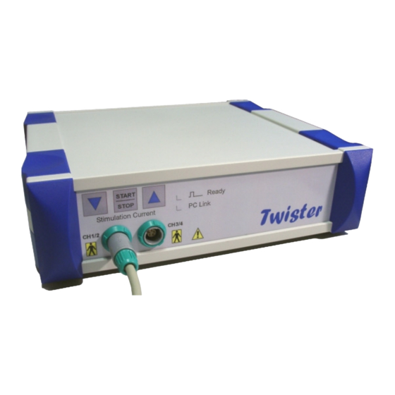
Page 11: Front Side Description
Connector for stimulation channels 3 and 4 Power: Power supply indicator (switched on -> green) Ready: Stimulator is ready to deliver stimulation pulses (yellow) PC Link: PC connected, control software started (green) ® TWISTER Softwareversion 1.19 Page 11 of 46 Version 1.19-4 / 2010-05-31... -
Page 12: Control Outputs And Inputs At The Rear Side Of The Device
4.2 Control outputs and inputs at the rear side of the device ® Power module: Power switch to turn TWISTER on and off USB-Host Connector: USB cable connector to PC Footswitch: External footswitch connector Trigger Out: TTL trigger output for connection to third party monitoring systems 4.2.1 Description of the combination with third party devices... -
Page 13: Twister Start Up
® Now the TWISTER PC software can be started. After a correct installation the green LED ® light “PC Link” at the front side of the TWISTER indicates a correct operation. ® TWISTER Softwareversion 1.19 Page 13 of 46 Version 1.19-4 / 2010-05-31... - Page 14 If the TWISTER is not connected to the power supply or not switched on, the following error message appears (Figure 2). ® Figure 2: Error message, TWISTER not connected to the power supply or switched off ® TWISTER Softwareversion 1.19 Page 14 of 46 Version 1.19-4 / 2010-05-31...
- Page 15 Figure 3: Incorrect USB device driver installation or USB link cable not properly connected ® Connect (if applicable) the USB link cable to the connector at the rear side of the TWISTER and to the PC’s USB connector. Then push the <No> button and the error message will disappear.
- Page 16 ® ® If TWISTER is not connected to the PC via the USB link cable the TWISTER software can be started in DEMO mode by pushing the <Demo> button. This mode shows you a flashing message „Demo-Mode“ at the bottom of the main window (Figure 5). To leave the demo mode, the software must be closed by pushing the <Quit>...
-
Page 17: Twister ® Shut Down
„Power“ LED light is turned off. If the PC is still switched on, the green „PC Link“ LED remains on. This function can be compared to a sleep mode. By switching off the PC or ® disconnecting the USB link cable the TWISTER is switched off completely. ®... -
Page 18: Twister Operation
® 5 TWISTER operation 5.1 Main window controls The main window is divided in several control groups. Figure 6 shows the controls to setup the pulse shapes for single and burst stimulation, the stimulation frequency as well as the controls for sequential stimulation. - Page 19 1 (CH1/2) for channel 1 or 2, or connector 2 ® (CH3/4) for the channels 3 or 4 at the front side of the TWISTER Sequence: Switching sequential stimulation on or off. In this mode the selected number of stimulation pulses will be fired.
- Page 20 The double arrow buttons increase or decrease the stimulation current in steps of 1 mA, single arrow buttons in steps of 0.1 mA. ® At the TWISTER front side you can also find two buttons labelled with arrows. They have the same functionality as the double arrow buttons in the software interface. Holding down the buttons for a long time increases or decreases the current continuously.
- Page 21 A program name can be edited in the yellow range „Program:“ (Figure 5) above the signal graph before a program is stored. It helps to identify the program. ® TWISTER Softwareversion 1.19 Page 21 of 46 Version 1.19-4 / 2010-05-31...
- Page 22 The controls in the lower part of the main window (Figure 10) contain the main functions of ® the stimulator TWISTER ® Figure 10: TWISTER main controls Help: Help window with short instructions Single / Burst / Shape: Pulse type selection for single pulses, burst pulses or pulse shapes. The active button is marked in yellow colour.
- Page 23 Status Display (Performance): With the key combination <Ctrl><Shift><F1> status indicators are displayed ® to check the performance of the PC system controlling the TWISTER hardware. Contact the service to get more information about the status controls. Figure 12: Pulse shape selection The selected pulse shape is displayed in the pulse preview (Figure 11).
- Page 24 <Stop>. Unnecessary controls or those which are not allowed to be changed during a running stimulation are disabled and dimmed (Figure 14). Start / stop can also be controlled by the ® START/STOP labelled button at the front side of the TWISTER ® TWISTER Softwareversion 1.19 Page 24 of 46 Version 1.19-4 / 2010-05-31...
- Page 25 (Figure 15). Additionally a beep tone indicates this warning. Figure 15: Flashing energy display in case of overshooting maximum pulse energy ® TWISTER Softwareversion 1.19 Page 25 of 46 Version 1.19-4 / 2010-05-31...
- Page 26 Figure 16: Stimulation frequency is too high to stimulate complete pulse shapes, the frequency display flashes ® If the PC performance is too low to control the stimulator TWISTER , an error message appears (Figure 17). If this message continuous to appear after all other applications have been closed, the PC is not suitable for this application (cp.
-
Page 27: Main Window Indicators
Wait a moment before starting the first stimulation in this case. Figure 17: System performance too low ® Quit: Quit the TWISTER application program 5.2 Main window indicators Energy [mJ]: Pulse energy display during a running stimulation. If the value exceeds 50 mJ the stimulation will be discontinued and the display flashes . -
Page 28: Pulse Shape Editor
If a pulse shape does already exist it will be displayed in the pulse graph. It can be changed or a new shape can be drawn. Figure 18: Pulse shape editor ® TWISTER Softwareversion 1.19 Page 28 of 46 Version 1.19-4 / 2010-05-31... -
Page 29: Drawing A New Pulse Shape
(Figure 19) the pulse shape can be stored together with a name, helping to identify it, using the <Save> button. This key is disabled, if no pulse shape exists in the pulse graph area. Figure 19: Drawn pulse shape ® TWISTER Softwareversion 1.19 Page 29 of 46 Version 1.19-4 / 2010-05-31... - Page 30 20mA Amplitude value in pulse shape [%] * selected stimulation current in main window [mA] Stimulated current [mA] = -------------------------------------------------------------------------------------------------------------------- The stimulated current is 16mA in this case. ® TWISTER Softwareversion 1.19 Page 30 of 46 Version 1.19-4 / 2010-05-31...
-
Page 31: Changing An Existing Pulse Shape
<Max. Time [ms]>. Figure 20: Changing an existing pulse shape • By pushing the button <Open>, stored waveform files for further operation can be opened. ® TWISTER Softwareversion 1.19 Page 31 of 46 Version 1.19-4 / 2010-05-31... - Page 32 (Figure 21). Choose or generate a pulse shape and start the stimulation again. Figure 21: Pulse shape chosen as pulse type but no shape selected ® TWISTER Softwareversion 1.19 Page 32 of 46 Version 1.19-4 / 2010-05-31...
-
Page 33: Basic Safety Instructions
Additionally all locally valid safety instructions and requirements to avoid harms have to be followed. 6.2 Operator obligation ® The operator is obliged, to allow only those staff working with the stimulator TWISTER , who ❒ are familiar with the TWISTER ®... -
Page 34: Dangers Using The Twister ® Stimulator
® 6.4 Dangers using the TWISTER stimulator ® The TWISTER stimulator is developed and built according to the current safety related standards. Nevertheless, certain risks for users or third parties can occur as well as ® damages on TWISTER ®... - Page 35 Sharp-edged items should not be placed close to the patient. Unnecessary high stimulation currents should be avoided. After having ® switched to another configuration or after having switched on the TWISTER device, the stimulation current should be checked before starting stimulation! ®...
- Page 36 The nerve stimulator TWISTER is intended for use In the electromagnetic environment specified below. The ® customer or the user of the nerve stimulator TWISTER should assure that it is used in such an environment. Compliance Electromagnetic environment - guidance Emission test ®...
- Page 37 ® radiated RF disturbances are controlled. The customer or the user of the nerve stimulator TWISTER can help prevent electromagnetic interference by maintaining a minimum distance between portable and mobile RF ®...
- Page 38 ® The nerve stimulator TWISTER is intended for use in the electromagnetic environment specified ® below. The customer or the user of the nerve stimulator TWISTER should assure that it is used in such an environment. Immunity- IEC 60601 -...
- Page 39 ® ® TWISTER is used exceeds the applicable RF compliance level above, the nerve stimulator TWISTER should be observed to verify normal operation. If abnormal performance is observed, additional measures may be ®...
-
Page 40: Preventing Electromagnetic Interferences
❒ Appropriate installation, transport, storage, start-up, operation and maintenance according to the user’s manual and all safety requirements and standards ❒ No arbitrary constructive changes at the nerve stimulator TWISTER ® ❒ No arbitrary services or repairs (repairs have to be done by the manufacturer only) ❒... -
Page 41: Safety Instructions
Caution: Indicates the danger for system parts or a possible impairment ® of the stimulator’s functionality TWISTER Type BF applied part (stimulation cable) Symbol indicates the conformance with the appropriate EU directives 0535: Identification number if the notified body ®... -
Page 42: Safety Measures During Normal Operation
7.5 Constructional changes at TWISTER Constructional changes and repairs are allowed to be done by the manufacturer only. 8 Copy right The copy right of the user’s manual is preserved by the Dr. Langer Medical GmbH Waldkirch, Germany. 9 User’s manual copying The user’s manual must not be copied without the approval by the manufacturer. -
Page 43: Technical Data
TTL trigger output, pulse width 200 µs, high active USB connector: B Type, meets USB 1.0 specification Power fuses: 2 X 200 mA/T Safety class I with protective earth conductor Protection class IP40 ® TWISTER Softwareversion 1.19 Page 43 of 46 Version 1.19-4 / 2010-05-31... -
Page 44: Serial Number Design
Twister Consecutive No. Calendar week Year of manufacture 12 Disposal of waste ® The TWISTER stimulator has to be disposed according to the locally valid instructions and standards for electronic scrap. 13 Cleaning ® The TWISTER device has to be cleaned with a moist cloth or disinfection by wipe. -
Page 45: Accessories
15 Accessories Please consider the accessories catalogue of the Dr. Langer Medical GmbH for detailed information on stimulation probes, needle electrodes and adhesive surface electrodes as well as connecting cables and other accessories. 16 PC performance requirements Operating system: Windows 2000 Prof. -
Page 46: Manufacturer Address
17 Manufacturer address Dr. Langer Medical GmbH Fabrik Sonntag, Haus 4a 79183 Waldkirch Germany Phone: +49 (0) 76 81 / 47 45 4 - 0 Fax: +49 (0) 76 81 / 47 45 4 - 29 http://www.neuromonitoring.eu info@neuromonitoring.eu ® TWISTER Softwareversion 1.19...
Need help?
Do you have a question about the TWISTER and is the answer not in the manual?
Questions and answers