Advertisement
Quick Links
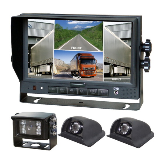
MO136CW087CS4012 Quick
Connection – Three-Camera System
Your system might not come with all selective accessories shown above. Pictures are for demonstration purpose only; actual look may vary.
Quick Connection Instructions (Please refer to accessories above, the connection diagram on next page, and Operating Instructions Manual.)
1.
Connect the 22-pin cable socket coming out of the monitor to the "22-pin power
A/V cable" (part A). Note the engraved arrows on the sockets from both ends
should be aligned (same for all socket connections).
2.
Connect the single red color wire (marked with "VCC" tag) for positive power
supply; connect the single black color wire (marked with "GND" tag) for ground.
3.
(Step 3-5 for connecting the rear view camera) Connect the single brown
colored wire (marked with "CAMERA B TRIGGER" tag) to the positive wire of
vehicle's reverse circuit or backup light circuit. (For auto camera activation when
vehicle in reverse mode function only, skip if the function is not preferred.)
4.
Connect the brown color 4-pin socket (marked with "CAMERA BACK" tag) to the
female end of a "30 feet 4-pin camera connecting extension cable" (part J);
Connect the other end of the 30-feet extension cable to the female 4-pin socket
of the "4-pin camera power A/V to RCA adapter/connector" (part H). (Note, if
you purchased additional extension cable, connect it to the first 30-feet extension
cable before connecting to the 4-pin camera adapter.)
5.
Connect the yellow RCA video socket, the white RCA audio socket (skip if your
camera dos not have audio capability or audio is not needed), and the power
socket of the "4-pin camera power A/V to RCA adapter/connector" (part H) to
the rear view camera's yellow RCA video socket, the white RCA audio socket
(skip if your camera does not have audio capability), and the power socket.
6.
(Step 6-8 for connecting the left side view camera) Connect the single
white colored wire (marked with "CAMERA L TRIGGER" tag) to the positive wire
B. Front Panel A/V Input
A. 22-pin Power A/V
Cable
Cable
G. Angle Adjust Screws
F. Remote Control
Copyright © 2008-2012, All Rights Reserved. [MO136CW087CS4102_3Camera_Instruction.pdf - Page 1]
C. Standard Mount Bracket
H. (2) 4-pin Camera Power
A/V to RCA
Adapter/Connector
of vehicle's left turn signal light circuit. (For auto camera activation with left turn
signal light function only, skip if the function is not preferred.)
7.
Connect the white color 4-pin socket (marked with "CAMERA LEFT" tag) to the
female end of a "15 feet 4-pin camera connecting extension cable" (part I);
Connect the other end of the 15-feet extension cable to the female 4-pin socket
of the "4-pin camera power A/V to RCA adapter/connector" (part H).
8.
Connect the yellow RCA video socket and the power socket of the "4-pin camera
power A/V to RCA adapter/connector" (part H) to the first side view camera's
yellow RCA video socket and the power socket.
9.
(Step 9-11 for connecting the right side view camera) Connect the single
blue colored wire (marked with "CAMERA R TRIGGER" tag) to the positive wire of
vehicle's right turn signal light circuit. (For auto camera activation with right turn
signal light function only, skip if the function is not preferred.)
10. Connect the blue color 4-pin socket (marked with "CAMERA RIGHT" tag) to the
female end of a "15 feet 4-pin camera connecting extension cable" (part I);
Connect the other end of the 15-feet extension cable to the female 4-pin socket
of the "4-pin camera power A/V to RCA adapter/connector" (part H).
11. Connect the yellow RCA video socket and the power socket of the "4-pin camera
power A/V to RCA adapter/connector" (part H) to the second side view camera's
yellow RCA video socket and the power socket.
12. Please properly preserve other cables, wires, sockets for future upgrades.
Reprint by Rocky Americas Inc. [www.RockyAmericas.com]
E. Sun Shield
D. Universal Mount
Bracket
J. (1) 30 Feet 4-pin
I. (2) 15 Feet 4-pin
Camera Connecting
Camera Connecting
Extension Cable
Extension Cable
Advertisement

Summary of Contents for Rocky Americas MO136CW087CS4012
- Page 1 12. Please properly preserve other cables, wires, sockets for future upgrades. white colored wire (marked with “CAMERA L TRIGGER” tag) to the positive wire Reprint by Rocky Americas Inc. [www.RockyAmericas.com] Copyright © 2008-2012, All Rights Reserved. [MO136CW087CS4102_3Camera_Instruction.pdf - Page 1]...
- Page 2 System Function/Connection Diagram: (Diagram shows an optional 4 camera.) Reprint by Rocky Americas Inc. [www.RockyAmericas.com] Copyright © 2008-2012, All Rights Reserved. [MO136CW087CS4102_3Camera_Instruction.pdf - Page 2]...
Need help?
Do you have a question about the MO136CW087CS4012 and is the answer not in the manual?
Questions and answers