
Summary of Contents for SWIR Acuros CQD Series
- Page 1 User Manual ® ® Acuros Camera Acuros Camera User Manual ® ® June 16, 2020 Document Version 1.1 P a g e...
- Page 2 Inc. are under warranty as described in the sales conditions and standard warranty documents. SWIR Vision Systems has no other obligation or liability for defects than those set forth therein. No other warranty is expressed or implied. SWIR Vision Systems specifically disclaims the implied warranties of merchantability and fitness for a particular purpose.
- Page 3 1.2 ..Scope ........................... 8 1.3 ..Order Description ........................ 9 1.4 ..Safety Considerations ......................9 1.5 ..SWIR Vision Systems, Inc. Product Global Limited Warranty ..........9 Acuros CQD Camera Product Data Sheet ................11 Camera Mechanical Interfaces ..................12 3.1 ..
- Page 4 User Manual ® ® Acuros Camera 7.2 ..Frames per Second (FPS) ....................34 7.3 ..Set Exposure Time ......................34 7.4 ..Windowing Settings ......................34 7.5 ..Pixel Format ........................35 7.6 ..Mirror ..........................35 7.7 ..Binning ..........................35 7.8 ..
-
Page 5: Table Of Contents
Acuros Camera Table of Figures Figure 1: SWIR Vision Systems Acuros CQD Camera Product Data Sheet ........11 Figure 3: Acuros CQD 1920 USB3 with F-mount ................12 Figure 4: Acuros CQD 1920 GigE with F-mount ................13 Figure 5: Acuros CQD 1280 USB with C-mount ................14 Figure 6: Acuros CQD 1280 GigE with C-Mount ................ - Page 6 User Manual ® ® Acuros Camera Figure 31: Settings File Dialog Box ....................39 Figure 32: SVS ImageIR Export, Contrast Enhancement, Histogram, and Output Interface ..39 Figure 33: General Purpose Output Timing Relative to Trigger ............ 41 Figure 34: SVS ImageIR Image Software NUC Interface ..............44 Figure 35: Sample Histogram, uncorrected flat field image............
- Page 7 User Manual ® ® Acuros Camera Table 12: Quick copy-and-paste reference table for common exposure times with Master Clock set to Lo............................57 Document Revisions Version Date Document Changes Number 10/9/2019 Initial Document 6/16/2020 Updates for SVS ImageIR rev 2.0A29 and higher P a g e...
-
Page 8: Table 1. List Of Camera Models Covered By This User Guide
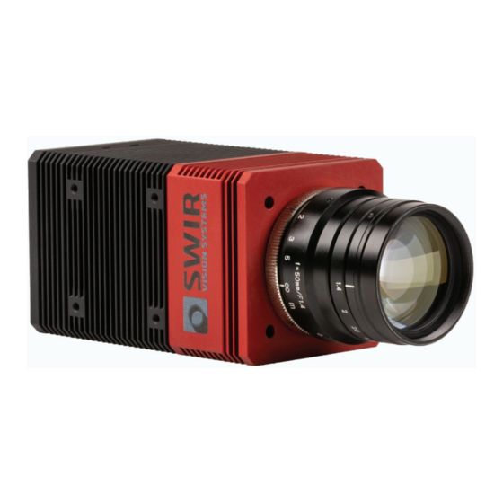
® camera line touts high speed, triggerable, area array VIS-SWIR imaging (0.4-1.7 um wavelengths), ideal for industrial inspection, security and surveillance, and scientific applications. The cameras are built around SWIR Vision Systems patented Colloidal Quantum Dot (CQD ® ) sensors. Unlike the InGaAs industry standard, CQD sensors leverage highly scalable monolithic semiconductor deposition techniques and result in the most affordable, highest resolution SWIR camera line on the market. - Page 9 ® ® repaired or replaced under warranty is covered for one hundred eighty (180) days from the date of return shipment by SWIR VISION SYSTEMS or for the remaining duration of the applicable Warranty Period, whichever is longer. 2. LIMITED WARRANTY. In accordance with the terms and conditions of and except as excluded or disclaimed in this document, SWIR VISION SYSTEMS warrants, from the Purchase Date, that all new Products will conform to SWIR VISION SYSTEMS’s published Product...
- Page 10 Customer, and for the cost of repackaging and returning the Product to Customer. Any non-warranty repair of a Product is warranted for one hundred eighty (180) days from the date of return shipment by SWIR VISION SYSTEMS to be free from defects in materials and workmanship only, subject to all of the limitations, exclusions and disclaimers in this document.
-
Page 11: Figure 1: Swir Vision Systems Acuros Cqd Camera Product Data Sheet
Windows GUI and SDK Windows GUI and SDK GenICam compliance Interface USB3 Vision or GiGE Vision USB3 Vision, GiGE Vision USB3 Vision, GiGE Vision Figure 1: SWIR Vision Systems Acuros CQD Camera Product Data Sheet 11 | P a g e... -
Page 12: Figure 3: Acuros Cqd 1920 Usb3 With F-Mount
User Manual ® ® Acuros Camera 3 Camera Mechanical Interfaces This section provides detailed mechanical drawing and corresponding camera specifications. For information on powering the camera and connecting it to your machine, see Section “Getting Started”. All cameras come with a tapped hole which is compatible with most tripods on the market. The C and F lens mounts are compatible with most standard lenses. -
Page 13: Figure 4: Acuros Cqd 1920 Gige With F-Mount
User Manual ® ® Acuros Camera Figure 3: Acuros CQD 1920 GigE with F-mount 13 | P a g e... -
Page 14: Figure 5: Acuros Cqd 1280 Usb With C-Mount
User Manual ® ® Acuros Camera Figure 4: Acuros CQD 1280 USB with C-mount 14 | P a g e... -
Page 15: Figure 6: Acuros Cqd 1280 Gige With C-Mount
User Manual ® ® Acuros Camera Figure 5: Acuros CQD 1280 GigE with C-Mount 15 | P a g e... -
Page 16: Figure 7: Acuros Cqd 640 Usb With C-Mount
User Manual ® ® Acuros Camera Figure 6: Acuros CQD 640 USB with C-Mount 16 | P a g e... -
Page 17: Figure 8: Acuros Cqd Gige With C-Mount
User Manual ® ® Acuros Camera Figure 7: Acuros CQD GigE with C-Mount 3.2 Thermal Management The Acuros CQD sensor generates heat which can affect device performance. The Acuros CQD camera uses an integrated thermo-electric cooling (TEC) unit in the sensor package for active thermal management. -
Page 18: Figure 9. Hirose Pinout Diagram
User Manual ® ® Acuros Camera 4 Electrical Interfaces and Specifications This section details the electrical connections for power and camera communications. 4.1 Specification and Camera Connectors Interface Camera Connector Specification Power Hirose HR10A-10R-12PB (71) See details listed below Trigger Low level CMOS 3.3V Unterminated SN74HCT1G125 compatible... -
Page 19: Figure 10. Led Indicator Status Diagram For Gige Cameras
User Manual ® ® Acuros Camera Name Type Notes Power Return Ground Protected by 600W @ 1.0ms PP Zener TVS. Receives Power Input 6V to 16V DC input. Reverse voltage protection to - 30VDC. Power Return Ground Trigger signal. Protected by ESD suppression to Trigger Input IEC61000-4-2 level. -
Page 20: Figure 11. Led Indicator Status Diagram For Usb3 Cameras
User Manual ® ® Acuros Camera Off: No ethernet connection. Network Activity Green on: Ethernet link. Green on blinking: Data is being transmitted or received. Network Off: No connection, 10Mbps connection, or 100Mbps connection. Connection Speed Green on: 1 Gps connection Table 4. -
Page 21: Figure 12: Acuros Cqd Camera With Protective Flange And No Sensor, An F-Mount Plate And Extender, And A C-Mount Plate
In this section we describe how to attach a lens and filter for each of the available lens mount types (C and F). Lenses should be SWIR coated and sized to cover the sensor in the selected Acuros CQD model to provide optimum imaging results. The table below shows the compatibility between each sensor size and each lens mount option. -
Page 22: Figure 13: Acuros Cqd Camera Showing C-Mount Attachment Process
User Manual ® ® Acuros Camera 5.1.1 Removing and attaching a lens and lens mount Use sufficient grounding whenever removing or attaching a lens mount to prevent ESD damage to the camera or sensor. 1. Place the camera on a stable, flat surface. 2. -
Page 23: Figure 14: Acuros Cqd Camera Showing F-Mount Alignment Pins On The Extender And F-Mount
User Manual ® ® Acuros Camera Figure 13: Acuros CQD Camera showing F-mount alignment pins on the extender and F-mount. Figure 14: Acuros CQD Camera with no lens mount. CQD sensor is visible inside the protective flange. 23 | P a g e... -
Page 24: Figure 16: F-Mount Detail Showing Spring-Loaded F-Mount Lens Pin
® Acuros Camera 7. Attaching a SWIR lens: a. F mount has a spring-loaded pin to secure the compatible 1/4-turn lens. Guide the lens into the F-mount so that the lens notch target will align with the pin. Rotate the lens ¼ turn. The locking pin will engage automatically. - Page 25 User Manual ® ® Acuros Camera 5.2 Sensor Cleaning Remove the lens mount as shown above. Use dry compressed air to remove loose particulate from the sensor lid surface. If additional cleaning is required, gently wipe with glass lens cleaning paper moistened with isopropyl alcohol.
-
Page 26: Figure 18. Acuros Cqd Camera Rear Panel Schematic Showing Power And Interface Connection Ports
User Manual ® ® Acuros Camera 6 Getting Started This section outlines the software and hardware installation processes. 6.1 Hardware Installation 6.1.1 Camera Electrical Interfaces All Acuros CQD Camera electrical interfaces are located on the back panel of the camera, shown below in Figure 1. - Page 27 User Manual ® ® Acuros Camera Important note: The camera must be connected in the following order: 1. Connect the communications cable (USB3 or GigE) between the camera and host machine. The order of these connections is unimportant. The USB3 status light will turn green once connected.
-
Page 28: Figure 21: Svsimagir Software Installation Screen
6.2 Software Installation The SVS ImagIR software is designed for a PC with the Windows 10 operating system. 1. Insert the SWIR Vision Systems thumb drive and run the file named SVSImagIR20A37 or higher. 2. Click “immediate installation” to proceed. - Page 29 User Manual ® ® Acuros Camera 4. A prompt to install the Pleora eBUS SDK software will appear after the SVS ImagIR software is installed. 5. At the Pleora InstallShield Wizard screen, click “next” 6. If you agree with the terms of the license agreement, click on the “I accept the terms in the license agreement”...
- Page 30 User Manual ® ® Acuros Camera 7. Click “install” to continue. We recommend selecting both the GigE and the USB3 drivers. Press “continue” to complete the process. 8. Once complete, click “finish” to exit the installer. 9. The SVS ImagIR software is launched from the programs menu or by using the new shortcut on the desktop.
-
Page 31: Figure 23: Svs Imagir Graphical User Interface Displaying A Flat Field Image And Histogram
User Manual ® ® Acuros Camera 6.3 Connecting to the Camera 6.3.1 Opening the Software Open the installed software, SVSImagIR. The software revision number located at the top left of the graphical user interface (GUI) and should read SVSImagIR20A37 or higher. Earlier release versions have reduced functionality. -
Page 32: Figure 24. General Flow For Image And Display Enhancement
User Manual ® ® Acuros Camera Important note about Imaging The GUI and image portion of this guide is designed for the user to begin by connecting the camera and starting the video to see images, then move to non-uniformity correction, contrast enhancement, and other features. -
Page 33: Figure 25: Svs Imagir Image And Video Controls
User Manual ® ® Acuros Camera 7 Software and Image Controls Important note: The field button must be pressed for GUI parameter value changes to take effect. For example, the “Set Exposure Time” button must be pressed after entering a new number in the “Set Exposure Time”... -
Page 34: Table 7: Maximum Frames Per Second For Different Windowing Settings
User Manual ® ® Acuros Camera 7.2 Set Frame Time Sets the frame time of the camera. The frame time cannot be set to a smaller value than the exposure time. 7.3 Frames per Second (FPS) The actual frames per second (FPS) output from the camera and the target FPS are displayed below the Set Frame Time button. -
Page 35: Table 8: Table Showing Windowing Maximums For Each Acuros Cqd Product
User Manual ® ® Acuros Camera Format Width Height 1280 1024 1920 1080 Table 8: Table showing windowing maximums for each Acuros CQD product 7.5.1 Set Width This value sets the total number of pixels read by the ROIC in the horizontal axis. The value range is 64 to 1920 pixels and must be a multiple of 16. -
Page 36: Figure 26: Svs Imagir Trigger Mode Menu
User Manual ® ® Acuros Camera 7.9 TriggerMode Image capture is triggered in three way, internal, external, and external PWM, and is set using the TriggerMode pull Figure 26: SVS ImagIR Trigger Mode Menu down menu. 7.9.1 Internal Trigger Internal trigger is used by the CSV export feature and uses the exposure time set in the user interface. -
Page 37: Figure 28: Pwm Trigger Timing Diagram
User Manual ® ® Acuros Camera rising edge and the next trigger’s rising edge. Minimum trigger periods and trigger delay values are determined by the Acuros CQD camera format and are listed in the table below. Figure 28: PWM Trigger timing diagram PWM Trigger Variables Low Speed Clock High Speed Clock... -
Page 38: Figure 29: Master Clock Pull-Down Menu
User Manual ® ® Acuros Camera 7.10 Master Clock The Acuros CQD Camera Master clock has two settings, High and Low and governs the sensor readout IC frequency. Figure 29: Master Clock Pull-Down Menu Low master clock can be used with the Mono14 pixel format and provides guaranteed 14bit precision on the camera’s output imagery. -
Page 39: Figure 31: Settings File Dialog Box
User Manual ® ® Acuros Camera become the new power-on defaults. Two-point Software NUCs and Contrast Enhancement settings are not saved and will be lost with a power cycle. The Load Factory Defaults command can be used to reset all the Acuros CQD Camera software parameters to their original (factory) values. - Page 40 User Manual ® ® Acuros Camera 7.14.1 Auto-Contrast Enhancement (ACE) Auto-contrast enhancement (ACE) selects a percentile of the camera output range to expand onto the full display range. ACE is enabled by checking the box to the left of the ACE text with typical settings of 2-5% in the box on the left and 95-98% on the right.
-
Page 41: Figure 33: General Purpose Output Timing Relative To Trigger
User Manual ® ® Acuros Camera 30sec) and will record all the frames output from the camera during the capture time. When using the default time setting of 30 seconds, if the camera is set for less than 30 fps, the total video time will be proportionally shorter;... - Page 42 User Manual ® ® Acuros Camera 7.15.5 Full Screen Clicking the Full Screen button between the camera image and the histogram generates a separate window containing the live image which can be moved or expanded to full screen. This only works when the camera video is running. 7.15.6 Scrolling 1.
- Page 43 User Manual ® ® Acuros Camera 8 Non-Uniformity Correction (NUC) The Acuros CQD Camera uses two-point non-uniformity correction to compensate for pixel to pixel spatial non-uniformities across the sensor. This method uses a dark frame image and a light frame image, each averaged over 10 frames, to calculate an offset and a gain for each pixel. These values are stored in the software NUC gain matrix or the firmware NUC tables.
-
Page 44: Figure 34: Svs Imageir Image Software Nuc Interface
User Manual ® ® Acuros Camera 8.2 Software NUC Table Generation A software 2-point NUC table must be generated for imaging conditions other than those used by the firmware tables. Software NUC tables are unique to the camera settings used during creation of the dark and light frame images. -
Page 45: Figure 35: Sample Histogram, Uncorrected Flat Field Image
User Manual ® ® Acuros Camera 4. Adjust the light intensity and lens aperture so all the pixels are above the noise floor and below saturation (below 15K pixel-value, typically centered around 8500 pixel-value). 5. Click “create flat field”. 6. A Windows Explorer dialog box will prompt the user for a file name and location. Figure 35: Sample Histogram, uncorrected flat field image Creation of the Gain Table:... -
Page 46: Figure 37: Image On The Left Shows The Saturation Gray-Scale Artifact. Image On Right Shows
User Manual ® ® Acuros Camera Figure 37: Image on the left shows the saturation gray-scale artifact. Image on right shows application of normalization feature to eliminate the artifact. 46 | P a g e... -
Page 47: Figure 38: Firmware Nuc Pull-Down Menus
User Manual ® ® Acuros Camera 8.3 Firmware NUC Table Use Up to four firmware NUC tables are programmed into the firmware and can be generated either at the factory or by the user. The corresponding camera settings for each table are loaded automatically for each NUC table. -
Page 48: Figure 39: Svs Internal Advanced Features User Interface
Changing the controls from the default settings can result in overheating and possible damage to the camera electronics and sensor. Any change to the default settings must be done under the guidance of SWIR technical support and carries risk or damage to the sensor and camera. 48 |... - Page 49 Figure 28 and the current is displayed in the section of the user interface as in Figure 34. 9.2.2 TEC Microcontroller Code Upload 9.2.2.1 Equipment SWIR Vision Systems Camera and associated cables Host computer SVS ImagIR Camera software, Version 2.0A28 or higher Source of microcontroller (.hex) files 9.2.2.2 Setup 1.
-
Page 50: Figure 40: Svsimageir Image Settings And Nuc Interfaces
9.3 Firmware NUC Generation Custom NUC tables allow the user to adapt the SVS ImagIR output to specific imaging conditions. Please contact SWIR Vision Systems for more information. There are three main steps to creating firmware NUCs: Data (image) collection, generating NUC tables using Python scripts, uploading the new tables, and linking the exposure time to these tables. -
Page 51: Figure 41: Sample Raw Files For 4 Different Exposure Times
User Manual ® ® Acuros Camera a. In the camera software, make sure that the “Mirroring” is turned OFF for both vertical and horizontal b. PixelFormat is set to Mono14. c. Turn off FW NUCS: Set NucEnable to (0) Offset Off/ Gain Off d. -
Page 52: Figure 42: Sample Nuc Files Output From The Python Scripts
1. Transfer the NUC/Raw Files folder to the Python execution machine. 2. Open the GainTableGen.py and BadPixelFix_2.py Python scripts using Spyder or your preferred Python environment. For best results, use scripts provided by SWIR Vision Systems. 3. The Gain table script output CSV files will have the names Gain_0, Gain_1, Gain_2 and Gain_3. -
Page 53: Figure 43: Firmware Upload And Ptc Collection Interface
User Manual ® ® Acuros Camera 9.4 Firmware NUC Upload Firmware NUC tables are in a CSV format and can be uploaded one file at a time or as an entire directory. Each firmware NUC table needs to be linked to its specific exposure time in order to function properly. -
Page 54: Figure 45: Svs Imagir Finished Loading Dialog Box
User Manual ® ® Acuros Camera 4. The NUC table can take up to 15 min to upload. Blocks Transferred will count upward; however, the GUI may stop responding or appear locked-up during the process. Do not close or restart the software. 5. - Page 55 User Manual ® ® Acuros Camera Before using the NUC tables you must link each to their correct exposure time as described in Section 9.4.4. 55 | P a g e...
-
Page 56: Figure 46: Hex-Decimal Converter, Command, And Message Byte Fields
User Manual ® ® Acuros Camera 9.4.4 Link Exposure Time to Each NUC Table after Upload Each firmware NUC is created with an exposure time that must be linked to the table after upload. This is done via the Send Host Message and uses Hex representation for the assigned NUC table and exposure time. -
Page 57: Figure 47: Command And Message Byte Fields Linking Nuc Table 3 To A 5.5Ms Exposure Time
User Manual ® ® Acuros Camera 4. Click Send Host Message. Figure 47: Command and Message Byte Fields linking NUC Table 3 to a 5.5ms exposure time. 5. Verify that it worked by enabling NucTable 3 and NucEnable is enabled. You will see that the SetExposure control is disabled and set to 5.55ms. -
Page 58: Figure 48: Svs Imagir Title Bar Showing Firmware Versions
The installed firmware versions are found in the title bar of the SVS ImagIR GUI. Figure 48: SVS ImagIR Title Bar showing firmware versions Upload the Microcontroller Firmware first for proper camera operation. 9.5.1 Equipment SWIR Vision Systems Camera and associated cables Host computer SVS ImagIR Camera software Source of microcontroller (.hex) and FPGA Figure 49: SVS ImagIR Firmware firmware (.rpd) files... - Page 59 User Manual ® ® Acuros Camera d. Verify that the correct version is running. This can be seen at the top of the SVS ImagIR window. 59 | P a g e...
- Page 60 User Manual ® ® Acuros Camera 9.5.4 FPGA file upload: 1. Click Upload FPGA Code. 2. A Windows Explorer dialog box will then open. Select the FPGA file which will be named camera_1920C_epcq64_122_auto.rpd or similar. Only files in the .rpd format will be available from this screen.
-
Page 61: Figure 50: Svs Imagir Firmware Upload And Ptc Interface
Photon Transfer Curve (PTC) Collection automates data generation for time-based European Machine Vision Association (EMVA) analysis, an industry standard for optical sensor characterization. Usually an internal SWIR process, this brief overview is included for completeness. Figure 50: SVS ImagIR Firmware... - Page 62 User Manual ® ® Acuros Camera 10 Software Command Protocol 10.1 UART Command Protocol Communication between the host (PC) and camera takes place by way of the transmission of data packets from one to the other. Communication is always initiated by the host in the form of a host message packet (described below).
- Page 63 User Manual ® ® Acuros Camera command byte MSB MSB of host command message bytes 1 to 256 message data bytes checksum Checksum is currently not supported and should be set to 0x00. 10.1.2 Echo message format Once a command has been received and executed by the camera, it will be echoed back to the host for verification.
- Page 64 User Manual ® ® Acuros Camera 10.2 Settings and Memory The 1920C camera operates in accordance with a set of parameters that are located in the FPGA on the digital board in the system. Since FPGA contents are lost when power is lost, the camera parameters are loaded from a nonvolatile memory into the FPGA each time power is applied.
- Page 65 User Manual ® ® Acuros Camera Set “BulkParity” to “None” ( PvGenParameterArray::SetEnumValue("BulkParity", “None”)) g. When you open the serial port using PvDeviceSerialPort::Open, make sure to choose PvDeviceSerialBulk0 (PvDeviceSerialPort::Open(UARTDeviceAdapter, PvDeviceSerialBulk0) Once the above steps are complete, the UART Command Descriptions in Section 10.3.4 can be used to find the command format for changing the camera registers.
-
Page 66: Figure 51: Pleora Firmware Updater User Interface
User Manual ® ® Acuros Camera Figure 51: Pleora Firmware Updater User Interface 4. Select iPort -NTx… under either the Ethernet connection or the USB Host Controller. 5. Select the correct payload file (format.dfw) to upload. 6. The user is prompted when the upload is complete. It does not take long. 7. - Page 67 User Manual ® ® Acuros Camera 10.4 UART Command Descriptions The UART command set can be seen below in figure xx. Command Set Name Command Width Factory (bits) Value Value Default Get FPGA Version 0x0100 SetTestW SetTestW Get Micro Version SetTestWord SetTestW SetTestW...
- Page 68 User Manual ® ® Acuros Camera SetExposureLo SetTestWord SetTestW SetTestW GetTest SetTest GetTestWor 0x000a Word Word GetExposureLo GetTestWord GetTestW GetTestW SetTest GetTest GetTestWor 0x010a Word Word dGetTestWord SetExposureHi 0x000b SetTestW SetTestW GetTest SetTest GetTestWord SetTe Word Word stWord GetExposureHi GetTestWord GetTestW GetTestW SetTest...
-
Page 69: Figure 53. Uart Command Set
User Manual ® ® Acuros Camera GetNucTable 0x0118 0x0019 reserved 0x0119 reserved GetHmax 0x011a GetVmax 0x011b SetVideoFormat 0x001c GetVideoFormat 0x011c LoadFactoryDefaults 0x200 SaveSettings 0x201 GetTestWord SetNUCTablePointer 0x203 UploadNucTable 0x204 GetTestWo SaveCamParams EraseFpgaSectors 0x206 SendFpgaPage 0x207 SetMicroTestWord 0x208 GetMicroTestWord 0x209 StepDeserPhase 0x20a LoadRoicDefaults 0x20b... - Page 70 User Manual ® ® Acuros Camera Echo Packet Byte Contents 0x02 - STX 0x01 - LSB (message size – 1) 0x00 - MSB (message size – 1) FPGA version LSB FPGA version MSB 0x00 - Unused 0x00 - Unused 10.4.2 GetMicroVersion Returns the 16-bit version number of the microcontroller code.
- Page 71 User Manual ® ® Acuros Camera 0x00 - Command Byte MSB TestWord LSB TestWord MSB 0x00 - Unused Echo Packet Byte Contents 0x02 - STX 0x01 - LSB (message size – 1) 0x00 - MSB (message size – 1) 0x00 - (unused message byte) 0x00 - (unused message byte) 0x00 - Unused 0x00 - Unused...
- Page 72 User Manual ® ® Acuros Camera 0x02 - STX 0x01 - LSB (message size – 1) 0x00 - MSB (message size – 1) 0x03 - Command Byte LSB 0x00 - Command Byte MSB Hactive LSB Hactive MSB 0x00 - Unused Echo Packet Byte Contents...
- Page 73 User Manual ® ® Acuros Camera 10.4.7 SetHtotal Sets the total number of pixels per line. This is used only for configuring video test patterns in the camera and plays no role in normal camera operation. Command Packet Byte Contents 0x02 - STX 0x01 - LSB (message size –...
- Page 74 User Manual ® ® Acuros Camera 0x00 - Unused 10.4.9 SetVactive Sets the number of active lines per frame. This is used to define the ROI (region of interest) of the camera. Vactive must be a multiple of two lines. Minimum = 4 lines Maximum = 1080 lines Command...
- Page 75 User Manual ® ® Acuros Camera Vactive LSB Vactive MSB 0x00 - Unused 0x00 - Unused 10.4.11 SetVtotal Sets the total number of lines per frame. This is used only for configuring video test patterns in the camera and plays no role in normal camera operation. Command Packet Byte Contents...
- Page 76 User Manual ® ® Acuros Camera Vtotal LSB Vtotal MSB 0x00 - Unused 0x00 - Unused 10.4.13 SetOutputMux Configures the video output multiplexer pattern generator; MuxValue VideoOutput Horizontal Ramp 1 Tap Horizontal Ramp 2 Tap Vertical Ramp 1 Tap Vertical Ramp 2 Tap Frame 1 Tap Frame 2 Tap Command...
- Page 77 User Manual ® ® Acuros Camera Packet Byte Contents 0x02 - STX 0x01 - LSB (message size – 1) 0x00 - MSB (message size – 1) MuxValue 0x00 - Unused 0x00 - Unused 0x00 - Unused 10.4.15 SetInputMux Configures the video input multiplexer; MuxValue VideoOutput Horizontal Ramp...
- Page 78 User Manual ® ® Acuros Camera Packet Byte Contents 0x02 - STX 0x01 - LSB (message size – 1) 0x00 - MSB (message size – 1) MuxValue 0x00 - Unused 0x00 - Unused 0x00 - Unused 10.4.17 SetPeriodLo Sets trigger period (low 16 bits) when operating in internal trigger mode. This command, along with SetPeriodHi defines the internal trigger period as a 32 bit value.
- Page 79 User Manual ® ® Acuros Camera 0x00 (unused message byte) 0x00 - Unused Echo Packet Byte Contents 0x02 - STX 0x01 - LSB (message size – 1) 0x00 - MSB (message size – 1) Period Lo LSB Period Lo MSB 0x00 - Unused 0x00 - Unused 10.4.19...
- Page 80 User Manual ® ® Acuros Camera 0x01 - Command Byte MSB 0x00 (unused message byte) 0x00 (unused message byte) 0x00 - Unused Echo Packet Byte Contents 0x02 - STX 0x01 - LSB (message size – 1) 0x00 - MSB (message size – 1) Period Hi LSB Period Hi MSB 0x00 - Unused...
- Page 81 User Manual ® ® Acuros Camera Command Packet Byte Contents 0x02 - STX 0x01 - LSB (message size – 1) 0x00 - MSB (message size – 1) 0x09 - Command Byte LSB 0x01 - Command Byte MSB 0x00 (unused message byte) 0x00 (unused message byte) 0x00 - Unused Echo...
- Page 82 User Manual ® ® Acuros Camera ExposureLo MSB 0x00 - Unused Echo Packet Byte Contents 0x02 - STX 0x01 - LSB (message size – 1) 0x00 - MSB (message size – 1) 0x00 - (unused message byte) 0x00 - (unused message byte) 0x00 - Unused 0x00 - Unused 10.4.24...
- Page 83 User Manual ® ® Acuros Camera 10.4.25 SetExposureHi Sets the exposure time (high 16 bits) of the camera. This command, along with SetExposureLo defines the exposure time as a 32 bit value. The actual exposure time depends on the selected frame rate.
- Page 84 User Manual ® ® Acuros Camera 10.4.26 GetExposureHi Returns the value of the exposure time issued via the SetExposureHi command. Command Packet Byte Contents 0x02 - STX 0x01 - LSB (message size – 1) 0x00 - MSB (message size – 1) 0x0b - Command Byte LSB 0x01 - Command Byte MSB 0x00 (unused message byte)
- Page 85 User Manual ® ® Acuros Camera 10.4.27 SetMasterClock Configures the camera frame rate. A “Low” clock rate allows for a maximum camera frame rate of 30fps. A “High” clock rate allows for a maximum camera frame rate of 60fps. Value Rate High Command...
- Page 86 User Manual ® ® Acuros Camera 0x00 - Unused 0x00 - Unused 10.4.29 SetPixelConcealment Turns the defective pixel concealment feature on or off. Value Concealment Command Packet Byte Contents 0x02 - STX 0x01 - LSB (message size – 1) 0x00 - MSB (message size – 1) 0x12 - Command Byte LSB 0x00 - Command Byte MSB ConcealValue...
- Page 87 User Manual ® ® Acuros Camera 0x00 - Unused 0x00 - Unused 10.4.31 SetMirror Turns the horizontal and vertical mirroring on and off. Bit 0 = Horizontal Mirror Bit 1 = Vertical Mirror Command Packet Byte Contents 0x02 - STX 0x01 - LSB (message size –...
- Page 88 User Manual ® ® Acuros Camera 0x00 - MSB (message size – 1) MirrorValue 0x00 - Unused 0x00 - Unused 0x00 - Unused 10.4.33 SetNucEnable Turns the nonuniformity correction feature on and off. Gain and offset correction may enabled/disabled independently. Bit 0 = Offset Nonuniformity Correction Bit 1 = Gain Nonuniformity Correction Command...
- Page 89 User Manual ® ® Acuros Camera 0x00 - MSB (message size – 1) 0x0e - Command Byte LSB 0x01 - Command Byte MSB 0x00 (unused message byte) 0x00 (unused message byte) 0x00 - Unused Echo Packet Byte Contents 0x02 - STX 0x01 - LSB (message size –...
- Page 90 User Manual ® ® Acuros Camera 0x02 - STX 0x01 - LSB (message size – 1) 0x00 - MSB (message size – 1) 0x00 - (unused message byte) 0x00 - (unused message byte) 0x00 - Unused 0x00 - Unused 10.4.36 GetBinning Returns the value of the SetBinning command.
- Page 91 User Manual ® ® Acuros Camera 0x00 - MSB (message size – 1) 0x00 - Command Byte LSB 0x02 - Command Byte MSB 0x00 (unused message byte) 0x00 (unused message byte) 0x00 - Unused Echo Packet Byte Contents 0x02 - STX 0x01 - LSB (message size –...
- Page 92 User Manual ® ® Acuros Camera 92 | P a g e...
- Page 93 User Manual ® ® Acuros Camera 10.4.39 SetNucTablePointer This command precedes the uploading of a NUC table from the host software to the camera. It informs the camera which NUC table is being uploaded. Pointer values are as follows; Pointer Table Offset table 1 Gain Table 1...
- Page 94 User Manual ® ® Acuros Camera 10.4.40 UploadNucTable This command informs the camera that 4Kbytes of MUC table data will be sent over the USRT interface on the Pleora hardware. The camera will receive and process the data, then send an echo.
- Page 95 User Manual ® ® Acuros Camera 10.4.41 SetMicroTestWord Writes a test word to a register in the microcontroller. Used to test for active camera firmware Command Packet Byte Contents 0x02 - STX 0x01 - LSB (message size – 1) 0x00 - MSB (message size – 1) 0x08 - Command Byte LSB 0x02 - Command Byte MSB Test Word Lo Byte...
- Page 96 User Manual ® ® Acuros Camera 10.4.43 EraseFpgaSector Used for uploading/programming FPGA code into the camera. Erases a given sector number in the FPGA configuration Flash. Valid sector numbers are from 0 – 41. Command Packet Byte Contents 0x02 - STX 0x01 - LSB (message size –...
- Page 97 User Manual ® ® Acuros Camera Echo Packet Byte Contents 0x02 - STX 0x01 - LSB (message size – 1) 0x00 - MSB (message size – 1) 0x00 - Unused 0x00 - Unused 0x00 - Unused 0x00 - Unused 10.4.45 LoadRoicDefaults Loads the ROIC serial register with its default values.
- Page 98 User Manual ® ® Acuros Camera 10.4.46 SetRoicBit Sets (or clears) a bit in the ROIC serial register. A bit number and a bit value are specified in the command. Valid ranges are; bit_number 1 – 660 bit_value 0 or 1 The bit numbers correspond directly to the entries in the spreadsheet provided by Sensor Creations;...
- Page 99 User Manual ® ® Acuros Camera 10.4.47 GetBitAdc Gets the value of the BIT (built-in-test) ADC for the specified channel number. The valid range is; channel_number 0 – 9 The channel numbers map into various physical test points; Channel Name t_aout_bot t_aout_top t_an_1_top...
- Page 100 User Manual ® ® Acuros Camera 0x00 - Unused 10.4.48 SetConstant Sets the value of the constant used as a video test pattern (see SetInputMux). Valid range is; constant 0 - 16383 Command Packet Byte Contents 0x02 - STX 0x01 - LSB (message size – 1) 0x00 - MSB (message size –...
- Page 101 User Manual ® ® Acuros Camera 0x00 - Unused 0x00 - Unused 101 | P a g e...
- Page 102 User Manual ® ® Acuros Camera 10.4.50 SetDetorCom Sets the bias voltage on the detor. The bias voltage is related to the 8 bit code by the formula; Volts = (code/255) * 4.096V * 0.75 Command Packet Byte Contents 0x02 - STX 0x01 - LSB (message size –...
- Page 103 User Manual ® ® Acuros Camera 0x00 - Unused 10.4.52 SetAmpOffset Sets the offset voltage on the differential amplifiers. The offset voltage is related to the 8 bit code by the formula; Volts = (code/255) * 2.5V Command Packet Byte Contents 0x02 - STX 0x01 - LSB (message size –...
- Page 104 User Manual ® ® Acuros Camera 10.4.54 SetNucTable Selects which NUC table to apply to the video data stream. Table numbers range from 0 to 3. Command Packet Byte Contents 0x02 - STX 0x01 - LSB (message size – 1) 0x00 - MSB (message size –...
- Page 105 User Manual ® ® Acuros Camera 10.4.56 StepDeserPhase Increments or decrements the phase of the ADC deserializer clock by the specified number of counts. The purpose is to align the data bits for the eight channels. Inc/Dec = 0 decrement Inc/Dec = 1 increment Counts = number of steps, 256 maximum...
- Page 106 User Manual ® ® Acuros Camera 10.4.57 GetHmax Returns the native horizontal resolution of the camera. Values of 1920, 1280 and 640 are legal. Command Packet Byte Contents 0x02 - STX 0x01 - LSB (message size – 1) 0x00 - MSB (message size – 1) 0x1a - Command Byte LSB 0x01 - Command Byte MSB 0x00 (unused message byte)
- Page 107 User Manual ® ® Acuros Camera 10.4.59 SetNucExposure Sets the default exposure time for a given NUC table. NUC table numbers range from 0 to 3. Exposure time is four bytes. (See SetExposureLo & SetExposureHi commands.) Command Packet Byte Contents 0x02 - STX 0x04 - LSB (message size –...
- Page 108 User Manual ® ® Acuros Camera 0x00 - Unused 108 | P a g e...
- Page 109 User Manual ® ® Acuros Camera 10.4.61 SetVideoFormat Sets the video format for the CameraLink output. VideoFormat = 0; 14 bit video data VideoFormat = 1; 12 bit video data VideoFormat = 2; 10 bit video data VideoFormat = 3; 8 bit video data Command Packet Byte...
- Page 110 User Manual ® ® Acuros Camera 0x00 - Unused 110 | P a g e...
- Page 111 User Manual ® ® Acuros Camera 10.5 Software Command Protocol Appendices 10.5.1 Appendix_A: FPGA Serial Bus and Register Map Serial Bus The diagram below shows the serial bus timing for the FPGA interface. It is a read/write bus with 7 bits of addressing and 16 bits of data (e.g. up to 127, 16-bit registers). The first bit in the sequence defines either a read or write cycle.
- Page 112 User Manual ® ® Acuros Camera Register Map Address 0x00 FPGA Version 15..0 version Address 0x01 Micro Version 15..0 version Address 0x02 Test Register 15..0 version Address 0x64 Resets 15..4 unused readout_n mem_intf_n memctrl_soft_n memctrl_glob_n Bit 0 Memory Controller global reset Bit 1 Memory Controller soft reset Bit 2...
- Page 113 User Manual ® ® Acuros Camera 10.5.2 Appendix_B: Uploading FPGA Code FPGA configuration data is sent to the camera via a sequence of software commands. The data is received by the camera and programmed into FPGA configuration Flash memory. After the upload is finished, power must be cycled on the camera to invoke the new FPGA code.
- Page 114 User Manual ® ® Acuros Camera 1) At power-up the bootloader app looks at the state of Pin 20 on the microcontroller. 2) If Pin 20 is at a logic low, then the bootloader jumps directly to the main app which runs the camera.
- Page 115 User Manual ® ® Acuros Camera 8) Send each byte in the line to the bootloader app in the camera over the UART. 9) When one line is sent, wait for an ACK byte (0x00) from the camera. 10) Repeat steps 7 & 8 until all lines are sent. The 8 and 9 bytes of each line contain a “line type”...
- Page 116 User Manual ® ® Acuros Camera After the upload is finished the bootloader will jump to the main application and the camera will be active. The host app should verify the camera is functional with the use of the SetMicroTestWord/GetMicroTestWord commands.
- Page 117 User Manual ® ® Acuros Camera 10.5.5 Appendix_E: Defective Pixel Concealment The purpose of defective pixel concealment is to mask pixels whose behavior lies outside the normal, linear operating range of the camera. These can include (but are not limited to) “hot pixels”...
- Page 118 User Manual ® ® Acuros Camera A single horizontal defect is concealed by replacing it with the average of its nearest neighbors. Pix1 Pix2 Pix3 Pix2 = (Pix1 + Pix3)/2; b. Two consecutive defective pixels Pix1 Pix2 Pix3 Pix4 Pix2 = Pix1 Pix3 = Pix4 c.
- Page 119 User Manual ® ® Acuros Camera 119 | P a g e...
- Page 120 User Manual ® ® Acuros Camera Six consecutive defective pixels Pix1 Pix2 Pix3 Pix4 Pix5 Pix6 Pix7 Pix8 Pix2 = (3*Pix1 + Pix8)/4 Pix3 = (3*Pix1 + Pix8)/4 Pix4 = (Pix1 + Pix8)/2 Pix5 = (Pix1 + Pix8)/2 Pix6 = (3*Pix8 + Pix1)/4 Pix7 = (3*Pix8 + Pix1)/4 g.
- Page 121 User Manual ® ® Acuros Camera 4) Vertical Concealment Vertical concealment is affected by replacing the defective pixel with the pixel value directly above it. One implication of this is that pixels in the first row of an image cannot be concealed.
Need help?
Do you have a question about the Acuros CQD Series and is the answer not in the manual?
Questions and answers