Advertisement
Quick Links
Advertisement

Summary of Contents for Procom DGC-101X Series
- Page 1 OPERATING INSTRUCTIONS DGC-101X DGC 101X Rev: 1.0...
- Page 2 INDEX 1.0. Introduction 2.0. Specifications 2.1 Terminal Specifications 2.2 Power Supply Requirements 2.3 Battery Voltage Display 2.4 Inputs 2.4.1 Digital Inputs 2.4.2 Analog Inputs 2.4.2.1 Coolant Temperature and Fuel 2.4.2.2 Pressure Sensor 2.4.3 Charging Alternator Interface 2.5 MPU Input 2.6 Digital Outputs 2.7 Communication Ports 3.0.
- Page 3 12.5 View Fault History / Event 13.0. In Built Parameter 13.1 System Parameter 13.2 Engine Parameter 13.3 Protection Parameter 13.4 Edit Annunciation Parameter 13.5 Comm. RS485 parameter 14.0 Model selection 15.0 Technical Specifications 16.0. Dimensions...
- Page 4 1.0. Introduction This document details the in-built features, operating procedure requirements of the DGC101X Series modules. This document is subject to changes without prior notice. DGC101X series is designed on a common platform and provided variants for different level of functionality and economics.
-
Page 5: Specifications
2.0. SPECIFICATIONS 2.1 Terminal Specification Connection type Two-part connector. Male part fitted to module Female part supplied in module packing case - Screw terminal, rising clamp, no internal spring. Example showing cable entry and screw terminals of a 10 way connector. 2.2Power Supply Requirements Minimum supply 8V continuous... - Page 6 2.4 INPUTS 2.4.1 Digital Inputs Number 8 fully configurable Arrangement Connection to Ground Polarity Programmable as Normally Open or Closed Low Level Threshold <0.7 V Max Input Voltage +40V Min Input Voltage -40V Contact Wetting Current Open Circuit Voltage 2.4.2 Analog Input 2.4.2.1 Coolant Temperature and Fuel Measurement Type Resistance measurement by measuring voltage across sensor with...
- Page 7 2.4.3 Charging Alternator Interface Excitation Magnetizing Current 220mA @12V (Typical) 110mA @24V (Typical) Measurement Range 0-40V Accuracy 1% of reading Resolution 0.1V Whenever the generator is required to run, the terminal provides excitation current to the charge alternator field winding.
- Page 8 Isolation voltage 4KV Modbus Implemented Protocol on Request Internal Termination of 120 Ω 3.0. Salient Features, Measurement, Protection and Supervision 3.1 Salient Features 1. Fully field programmable either from front Keypad, through PC via USB or in field through modbus communication 2.
- Page 9 4.0. Digital Inputs and Outputs: 4.1 Digital Outputs No of Digital Out Puts Programmable Output Annunciation 1 Annunciation 2 Annunciation 3 Annunciation 4 User Contact User Contact could be assigned to any one of these functions ...
- Page 10 ground. This could just be pulse of around 100ms Note: There are some restriction on the assignment of the function to the Digital Inputs a) R. Start/Stop can not be selected along with either of R.Stop or R.start b) R.Start and R.Stop both must be assigned. Assigning only one is not allowed 5.0.
- Page 11 7.0. Installation For dimension details, see the section entitled Dimension latter in this document. 7.1 Terminal Description 7.1.1 DC Supply, Outputs and Inputs DESCRIPTION NOTES Negative DC Supply DC Supply Input (Negative) Positive DC Supply DC Supply Input (Positive) Solenoid Battery Positive to drive a Relay for Solenoid operation Crank Battery Positive to drive a Relay for cranking the engine...
- Page 12 SEN LLOP Connect to Oil pressure sensor SEN HWT Connect to High Water Temperature sensor SEN Fuel Connect to Fuel sensor SEN Oil Connect to Oil Temperature Sensor Input of MPU or W-Point from charging alternator MPU/W-Point 7.1.2 Configurable Digital Inputs DESCRIPTION NOTES Prog.
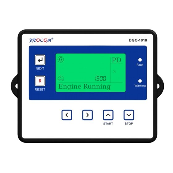
- Page 13 7.1.4 PC Configuration Interface Connector DESCRIPTION NOTES Socket for connection to PC with This is a standard USB type A to software. type B connector. 8.0. Display / Front Panel 8.1 Front Facia 128x64 pixels Graphical LCD Display for ease of readout. Parameters are displayed in English along with symbolic representation.
-
Page 14: Icon Description
S.No Description Next Key. The preceding section describes the functions associated with all keys. Reset Key. Back Key. Forward Key. Increment/Start Key. Decrement/Stop Key. The area below shall indicate the status of engine. If the engine is running, engine running is displayed. Warning LED. -
Page 15: Icons Description
OVER RPM The engine speed has risen above the programmed RPM alarm setting V Belt/Chg Alt The auxiliary charge alternator voltage is low LOW FUEL The level detected by the fuel level sensor is below the low fuel level setting. EMERGENCY STOP The emergency stop button has been depressed. - Page 16 9.3 Fault Related Warning Icons LLOP LLOP Warning shows in the display when Action LLOP is selected as warning. HWT Warning shows in the display when Action HWT is selected as warning. Oil Temperature Oil Temperature Warning shows in the display when Action Oil Temperature is selected as warning.
- Page 17 This icon shows the oil temperature of Fuel Sensor This icon shows the fuel of generator. Charging Alternator This icon shows the voltage of alternator. Voltage This icon shows the current date and time. 10.0 Keys & LEDs Description DGC101X has seven Keys provided on its front panel. The table below describes the operation of these.
- Page 18 LED Annunciations Description: DGC101X has 2 annunciations on its front panel. These announce the faults and warning of the system. Nomenclature Symbol Description Fault Fault This LED blinks in case of a fault Warning Warning This LED blinks in case of a warning 11.0.
- Page 19 Press START to Reset STOP to ESC If you press START Switch, it will reset the Service due hour. If you press STOP Switch, the service due hour will not reset. 12.3 Set Clock: Scroll Up and Down to select the Set Clock. Press Next Switch to enter in the Set Clock mode.
- Page 20 13.0. In built Parameter: The following tables give the detailed descriptions. Please note that 20sec of inactivity will take the unit back in normal mode and all the changes done shall be discarded. 13.1 System Parameter Parameter Explanation of Parameter Factory Setting Setting Range Name on LCD...
- Page 21 Sensor V1 These table are used when sensor type is selected as user LLOP 0-999 defined. Sensor R2 LLOP 0.0-10.0 Sensor V2 LLOP 0-999 Sensor R3 LLOP 0.0-10.0 Sensor V3 LLOP 0-999 Sensor R4 LLOP 0.0-10.0 Sensor V4 LLOP 0-999 Sensor R5 LLOP 0.0-10.0...
- Page 22 Fuel Sensor Select the installed sensor for Type A User Defined Fuel Type A There are many built in sensors Sam-0 to choose from. For sensors Sam-1 whose data is not in-built User Electronics defined can be selected and the Linear sensor data programmed.
- Page 23 Fuel 0-100 Sensor V7 Fuel 0-999 Sensor R8 Fuel 0-100 Sensor V8 Fuel 0-999 Sensor R9 Fuel 0-100 Sensor V9 Fuel 0-999 Sensor R10 Fuel 0-100 Sensor V10 Select the installed sensor for Type A User Defined Sensor Type A There are many built in sensors M&M to choose from.
- Page 24 0-9999 Sensor R4 0-300 Sensor V4 0-9999 Sensor R5 0-300 Sensor V5 0-9999 Sensor R6 0-300 Sensor V6 0-9999 Sensor R7 0-300 Sensor V7 0-9999 Sensor R8 0-300 Sensor V8 0-9999 Sensor R9 0-300 Sensor V9 0-9999 Sensor R10 0-300 Sensor V10 Select the installed sensor for Oil Type A...
- Page 25 parameter shall not be displayed GC(MURPHY) Disabled * User OIL R1 R1 to R10 = Resistance Value 0-9999 V1 to V10 = Corresponding Oil temperature in °C. User OIL V1 0-300 These table are used when sensor type is selected as user User OIL R2 0-9999 defined.
- Page 26 User OIL R10 0-9999 User OIL V10 0-300 Sensor Open User can select the action to be Warning Fault taken in case of sensor open, it Warning can be configured as a fault, or as None warning. Fault selection shall shut down the engine.
- Page 27 Din 1 Polarity Normally Open Normally Close Normally Open polarity of digital input can be changed either normally open or normally close. Digital Input 2 This can be assigned to any of Fuel the function from this list. Oil Level Oil Temp Emergency Fuel...
- Page 28 R Stop R Start None Din 3 Polarity Normally Open Normally Close Normally Open polarity of digital input can be changed either normally open or normally close. Digital Input 4 This can be assigned to any of Oil Temp the function from this list. Oil Level Oil Temp Emergency...
- Page 29 R. Start/Stop R Stop R Start None Normally Open Normally Close Din 5 Normally Open PolarityThe polarity of digital input can be changed either normally open or normally close. Digital Input 6 This can be assigned to any of the function from this list. Oil Level Oil Temp Emergency...
- Page 30 be changed either normally open Normally Open or normally close. Digital Input 8 This can be assigned to any of None the function from this list. Oil Level Oil Temp Emergency Fuel LLOP R. Start/Stop R Stop R Start None Din 8 Polarity The polarity of digital input can Normally Open Normally Close...
- Page 31 tolerated before stopping the Generator. This setting is not available if (4)&(5) are disabled. RPM can be selected through MPU Source or CAN Bus. CAN Bus Pick Up This parameter specifies the 200-3000 minimum RPM at which crank shall be terminated. Cnk Dsc Auto disconnects the crank Disabled...
- Page 32 Choke Pre If the programmable Digital output Disabled Disabled* time is programmed for “Heater 1-100 Sec /Choke” This parameter sets the time gap between this contact and crank. The crank will be activated after the programmed time has elapsed after this contact was activated. Choke Post If the programmable Digital output Disabled...
- Page 33 Action LLOP Select the action when LLOP Engine Shut Down Warning fault occurs. Engine Shut Down No Action HWT Trip Level Monitoring value of water 40-249 temperature above which HET Disabled* trip is generated. HWT Trip Delay Monitoring time for above. 1-100 Sec Action HWT Select the action when HWT...
- Page 34 any parameter of digital input 2 is selected. Digital Monitoring time for 1-100 Sec Input 3 Delay programmable digital input. Digital inputs are explained above. Action DIN 3 Engine Shut Down Warning Engine Shut Down No Action Select the action when any parameter of digital input 3 is selected.
- Page 35 Input 6 Delay Digital inputs are explained above. Action DIN 6 Select the action when any Engine Shut Down Warning parameter of digital input 6 is Engine Shut Down selected. No Action Digital Monitoring time for 1-100 Sec Input 7 Delay programmable digital input.
- Page 36 alternator fault occurs. Hooter ON Time Duration for which the hooter 1-100 Sec shall be ON, if not externally reset, while announcing a fault. Crank ON Time Maximum crank time. 1.0-20.0 Sec Crank Gap Time The delay between two 1-200 Sec successive cranks.
- Page 37 13.4 Edit Annunciation Parameter Ann HWT If desired, the HWT fault can be No Ann On Ann 1 announced at one of the ann. On Ann 2 Digital Output. On Ann 3 On Ann 4 No Ann Ann LLOP If desired, the LLOP fault can be No Ann On Ann 1 announced at one of the ann.
- Page 38 No Ann Ann Eng Running If desired, the running of the No Ann On Ann 1 engine can be announced at one On Ann 2 of the annunciation Digital On Ann 3 Output. On Ann 4 No Ann 13.5 Comm RS485 Parameter Device Id Modbus device ID.
- Page 39 Vibration 5Hz - 8Hz at +/- 7.5mm 8Hz – 500Hz 2g IP65 From front 16.0. Dimensions...
Need help?
Do you have a question about the DGC-101X Series and is the answer not in the manual?
Questions and answers