Table of Contents
Advertisement
Quick Links
Advertisement
Chapters
Table of Contents

Summary of Contents for MSSC GDMS-OMD14
- Page 1 USER ManUal GDMS-OMD14 ® Gear and Diesel engine Monitoring System Oil Mist online Detection System Part No.: 2 914 00 0000 Release: 160623 (revision 160704) Marschallstraße 4 • 66606 St. Wendel • Germany Tel. +49 6851 9127970 eMail: info@mss-hx.com • Web: www.mss-hx.com...
- Page 3 Kind of equipment: Gear and Diesel Monitoing System Oil Mist online Detection System Type - designations: GDMS-OMD14 are in compliance with following norms: En 55011, En 55022, En 61000-4-2, En 61000-4-3, En 61000-4-4, En 61000-4-5, En 61000-4-6, IEC 60068-2-1: 2007-03, IEC 60068-2-2: 2007-07,...
- Page 4 Unless notified, these operation instructions are applicable for: GDMS-OMD14 In case of a GDMS-OMD14 alarm, the operator should take appropriate actions to prevent an explosion or damages from the engine. The recommended measures of the engine manufacturer are to be followed.
- Page 5 GDMS-OMD14 ® User Manual Contents 1. System Description............... 1.1 2. Installation ..................2.1 3. Commissioning ................3.1 4. Performance / Maintenance Tests ..........4.1 5. Troubleshooting ................5.1 6. Repair ................... 6.1 7. Notes .................... 7.1 Release 160623 Page v...
- Page 6 GDMS-OMD14 ® User Manual Page vi Release 160623 (revision 160704)
-
Page 7: Table Of Contents
1.1.2. GDMS-OMD14 - Delivered Items .............1.4 1.1.3. GDMS-OMD14 - System Components ..........1.5 1.1.3.1. GDMS-OMD14 Evaluator ............1.5 1.1.3.2. Connectors and pin-out of the GDMS-OMD14 Evaluator ..1.8 1.1.3.3. GDMS-OMD14 Sensor and SOPS ..........1.9 1.1.3.4. Technical Data of GDMS-OMD14 Sensor and Evaluator ..1.11 1.1.4. - Page 8 GDMS-OMD14 ® User Manual Page viii Release 160623 (revision 160704)
-
Page 9: Components
LEL, Lower Explosion Level (50 mg/l), the oil mist detector will trigger an alarm. GDMS-OMD14 is also capable of detecting water vapour. Due to water vapour, corrosion on major parts inside the engine may occur which will damage the engine. - Page 10 User Manual Based on a widely-used principle of light measurement, GDMS-OMD14 does not have the disadvantages of some older OMD systems. The GDMS-OMD14 is a pipe- free system, with sensors mounted directly at the engine wall, it allows quick and exact measurement of oil mist concentration in each engine compartment.
- Page 11 GDMS-OMD14 ® User Manual Key benefits of the GDMS-OMD14 System 1. The oil mist is measured inside the engine where it develops. Therefore, the response time from the development of oil mist until the system raises an alarm is very short.
-
Page 12: Gdms-Omd14 - Delivered Items
GDMS-OMD14 ® User Manual 1.1.2. GDMS-OMD14 - Delivered Items Connecting up to 16 OMD14 sensors Redundant Serial Ring Bus 24V DC GDMS-OMD14 Evaluator Local Alarm System PC / display / printer Logger software (optional) Fig. 1.2. GDMS-OMD14 System Main components of GDMS-OMD14 system: 1. -
Page 13: Gdms-Omd14 - System Components
) and one reset button Reset The electronics and the display of the GDMS-OMD14 Evaluator are installed in a closed, shock-proofed, water, dust and EMC resistant aluminium case, protection class IP 67. The Evaluator can be mounted close to the engine or in the engine control room. - Page 14 GDMS-OMD14 ® User Manual After successful installation and testing by service technicians approved by MSS AG, the settings of the Evaluator should not be changed. The Evaluator does not require regular maintenance. Note: Firmware updates for the Evaluator will be available and may be applied to your system only by service technicians approved by MSS AG.
- Page 15 GDMS-OMD14 ® User Manual Fig. 1.4. Evaluator Dimensions Release 160623 Page 1.7 (revision 160704)
-
Page 16: Connectors And Pin-Out Of The Gdms-Omd14 Evaluator
GDMS-OMD14 ® User Manual 1.1.3.2. Connectors and pin-out of the GDMS-OMD14 Evaluator Connectors of the Evaluator Power Serial Data OMD14 OMD14 Relays Supply Link REL1-A RS232 +24V Alarm 1 +24V +24V Relay NC REL1-B RS232 Alarm 1 Relay NO REL1-C... -
Page 17: Gdms-Omd14 Sensor And Sops
SOPS functionality. GDMS-OMD14 does not have any movable mechanical parts and hence does not undergo any wear and tear. Fig. 1.6. Installation of SOPS and sensor Release 160623 Page 1.9... - Page 18 (Sensor). These components build a mechanical unit. The GDMS-OMD14 is mounted to the engine wall, separating the crank case with its Ex-category 2G requirements, from the non explosive engine room. The cylindrical Aluminium housing containing the electronic system is an assembly of circuit boards and electronic components.
-
Page 19: Technical Data Of Gdms-Omd14 Sensor And Evaluator
Power Supply: 24V DC +30/-25% (18 - 31V DC) Operating Current: max. 1.5 A Up to 16 (sixteen) GDMS-OMD14 Sensors can be connected. If the supply voltage is below 18V DC or higher than 31V DC no guarantee can be given that the system is working properly. - Page 20 GDMS-OMD14 ® User Manual 1.1.3.5. Important for users of Gas Engines for non intrinsically safe electric circuits rated voltage for power supply DC 24V, U = DC 30V rated voltage for RS 485 interface DC 24V, U = DC 30V...
-
Page 21: Intended Purpose
User Manual 1.1.4. Intended Purpose The use of a PC with the GDMS-OMD14 is only permitted by using equipment approved by MSS AG, i.e. interface converter, plugs, etc. MSS AG can only provide technical support if MSS AG approved equipment is used. -
Page 22: Materials Included
User Manual 1.1.5. Materials Included To the scope of supply of a GDMS-OMD14 System belongs one Evaluator for each engine, one sensor for each compartment with the appropriate SOPS (splash oil protection system), cables in the correct length, provided with the necessary plug-in connections as well as all seals, O-rings and small articles for the assembly. -
Page 23: Installation
Important for users of Gas Engines The GDMS-OMD14 has to be installed to the engine wall in the manner specified, that the appropriate component (electronic system) sits in the non explosive engine room outside the crank case and the intrinsically safe component (Sensor) sits inside the crank case with its Ex-category 2G requirements. -
Page 24: Installation Position
® User Manual 2.2. Installation Position The position for the GDMS-OMD14 sensors and SOPS in the engine wall must be chosen carefully. Using existing drilled holes, for example used by an old oil mist detection system, the installation is easy. -
Page 25: Wiring Diagram
Power supply Relay output Data link max. 16 GDMS-OMD14 Sensors Fig. 2.2 Principle Connection The connection for power supply, relay output, data link and connection of GDMS- OMD14 sensors is shown in this figure. It is possible to connect up to 16 sensors to one evaluator. - Page 26 GDMS-OMD14 ® User Manual Page 2.4 Release 160623 (revision 160704)
-
Page 27: Commissioning
• For more detailed information, please have a look at the Installation Manual! 3.2. Data Sampling As soon as a GDMS-OMD14 Evaluator is powered up, it starts the initial self check procedure and shows the READY Status if all pre-set conditions are fulfilled. This self check procedure is carried out in a certain cycle. -
Page 28: Alarm Resetting
The temperature alarm level is given in degree Celsius. Sensitivity Level Sensitivity mg/l 10.0 Alarm sensitivity levels must be set at the GDMS-OMD14 Evaluator. If alarm conditions are fulfilled, the firmware of the GDMS-OMD14 Evaluator triggers the corresponding alarm. In case of an alarm triggering, it is shown: •... -
Page 29: Settings & Parameters / Using The Evaluator
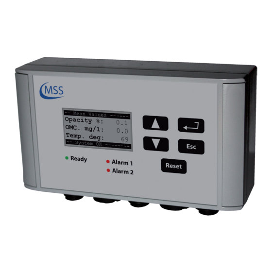
GDMS-OMD14 ® User Manual 3.4. Settings & Parameters / Using the Evaluator 3.4.1. Basic Usage of the Evaluator Using the Evaluator is very simple. It has got one 128x64 pixels LCD, four navigation buttons ( ), one reset button and three LEDs Reset indicating the system status. -
Page 30: How To Change A Value
GDMS-OMD14 ® User Manual 3.4.2. How to change a value In this example the change of the value “Display Brightness” is described. The screen we need to get to is Screen 1.3.3.1 - CPU Settings - Display Brightness. 1. Beginning with the default screen Screen 1.1 - Opacity % / OMC. mg/l / Temp. - Page 31 GDMS-OMD14 ® User Manual Fig. 3.4. Screen 1.3.3.1 as of step 9 By pushing twice, the Evaluator will restart and the default screen Screen 1.1 - Opacity % / OMC. mg/l / Temp. deg will be shown. Note: If you do not want to change the value while you are in step 8, press the button and the old value will return.
- Page 32 GDMS-OMD14 ® User Manual Page 3.6 Release 160623 (revision 160704)
-
Page 33: Menu Screen Overview
GDMS-OMD14 ® User Manual 3.4.3. Menu Screen Overview Screen 0.1 - Startup Screen ................3.8 Screen 1.1 - Opacity % / OMC. mg/l / Temp. deg ..........3.9 Screen 1.2 - Sensor values .................3.9 Screen 1.3 - Settings/Tests..................3.9 Screen 1.4 - System Version ................3.10 Screen 1.5 - Restart System? ................3.10... -
Page 34: Screen 0.1 - Startup Screen
GDMS-OMD14 ® User Manual Screen 0.1 - Startup Screen No action No action No action No action No action Reset This screen is displayed right after powering up the Evaluator. It shows the product name and the firmware version. This screen is shown for 5 seconds and will automatically jump to screen Screen 1.1. -
Page 35: Screen 1.1 - Opacity % / Omc. Mg/L / Temp. Deg
GDMS-OMD14 ® User Manual Screen 1.1 - Opacity % / OMC. mg/l / Temp. deg Screen 1.4 will be shown Screen 1.2 will be shown No action Screen 1.5 will be shown No action Reset This screen shows the average values of all sensors: the opacity in %, the oil mist concentraion in mg/l and the temperature in degree Celsius. -
Page 36: Screen 1.4 - System Version
GDMS-OMD14 ® User Manual Screen 1.4 - System Version Screen 1.1 will be shown Screen 1.3 will be shown Screen 1.3.1 (page 3.13) will be shown Screen 1.5 will be shown No action Reset This screen shows the product name and the firmware version. -
Page 37: Screen 1.2.1 - Sensor Values - Measured Values Sensor 1
GDMS-OMD14 ® User Manual The following screen is identical for each sensor and is only described once in this manual. Screen 1.2.1 - Sensor Values - Measured values sensor 1 The next connected sensor will be shown, in this case sensor no. 2... - Page 38 GDMS-OMD14 ® User Manual Page 3.12 Release 160623 (revision 160704)
-
Page 39: Screen 1.3.1 - System Settings
GDMS-OMD14 ® User Manual If you have entered either Screen 1.3.1, Screen 1.3.2, Screen 1.3.3 or Screen 1.3.4, pushing will make the Evaluator reboot and continue with Screen 0.1! Screen 1.3.1 - System Settings Screen 1.3.2 will be shown Screen 1.3.4 will be shown Screen 1.3.1.1 (page 3.15) will be shown... -
Page 40: Screen 1.3.4 - Test Functions
GDMS-OMD14 ® User Manual Screen 1.3.4 - Test Functions Screen 1.3.1 will be shown Screen 1.3.3 will be shown Screen 1.3.4.1 (page 3.23) will be shown will be shown No action Reset Via this screen you can access the testing features of the Evaluator. -
Page 41: Screen 1.3.1.1 - System Settings - Number Of Sensors
GDMS-OMD14 ® User Manual Screen 1.3.1.1 - System Settings - Number of sensors Screen 1.3.1.2 will be shown Screen 1.3.1.17 will be shown You may change the value if you have entered the PIN. Screen 1.3.1 (page 3.13) will be shown... -
Page 42: Screen 1.3.1.4 - System Settings - Tmp Main-Alarm Level
GDMS-OMD14 ® User Manual Screen 1.3.1.4 - System Settings - TMP Main-Alarm Level Screen 1.3.1.5 will be shown Screen 1.3.1.3 will be shown You may change the value if you have entered the PIN. Screen 1.3.1 (page 3.13) will be shown... -
Page 43: Screen 1.3.1.7 - System Settings - Opa Main-Alarm Relay
GDMS-OMD14 ® User Manual Screen 1.3.1.7 - System Settings - OPA Main-Alarm Relay Screen 1.3.1.8 will be shown Screen 1.3.1.6 will be shown You may change the value if you have entered the PIN. Screen 1.3.1 (page 3.13) will be shown... -
Page 44: Screen 1.3.1.10 - System Settings - Tmp Pre-Alarm Relay
PIN. Screen 1.3.1 (page 3.13) will be shown No action Reset With this setting, you can correct the numbering of the GDMS-OMD14 sensors, so that the sensor numbering matches the compartment numbering. Page 3.18 Release 160623 (revision 160704) -
Page 45: Screen 1.3.1.13 - System Settings - Max. Opa Increase
GDMS-OMD14 ® User Manual Screen 1.3.1.13 - System Settings - Max. OPA increase Screen 1.3.1.14 will be shown Screen 1.3.1.12 will be shown You may change the value if you have entered the PIN. Screen 1.3.1 (page 3.13) will be shown... -
Page 46: Screen 1.3.1.16 - System Settings - Sensor Dirty Delay
GDMS-OMD14 ® User Manual Screen 1.3.1.16 - System Settings - Sensor Dirty Delay Screen 1.3.1.17 will be shown Screen 1.3.1.15 will be shown You may change the value if you have entered the PIN. Screen 1.3.1 (page 3.13) will be shown... -
Page 47: Screen 1.3.2.1 - Alarm Inhibit - Hysteresis
GDMS-OMD14 ® User Manual Screen 1.3.2.1 - Alarm Inhibit - Hysteresis Screen 1.3.2.2 will be shown Screen 1.3.2.3 will be shown You may change the value if you have entered the PIN. Screen 1.3.2 (page 3.13) will be shown No action Reset Setting of Alarm Inhibit Hysteresis ranging from 2 to 15 °C. -
Page 48: Screen 1.3.3.1 - Cpu Settings - Display Brightness
GDMS-OMD14 ® User Manual Screen 1.3.3.1 - CPU Settings - Display Brightness Screen 1.3.3.2 will be shown Screen 1.3.3.2 will be shown You may change the value. Screen 1.3.3 (page 3.13) will be shown No action Reset Setting of display brightness in the range of 5 to 100. (5 = dark, 100 = bright) Screen 1.3.3.2 - CPU Settings - PIN for System Param... -
Page 49: Screen 1.3.4.1 - Test Functions - Ready Relay
GDMS-OMD14 ® User Manual Screen 1.3.4.1 - Test Functions - Ready Relay Screen 1.3.4.2 will be shown Screen 1.3.4.4 will be shown You may change the value if you have entered the PIN. Screen 1.3.4 (page 3.14) will be shown... -
Page 50: Screen 1.3.4.4 - Sensor Cleaning
GDMS-OMD14 ® User Manual Screen 1.3.4.4 - Sensor cleaning Screen 1.3.4.1 will be shown Screen 1.3.4.3 will be shown You may change the value if you have entered the PIN. Screen 1.3.4 (page 3.14) will be shown No action Reset Change the value to “ON”... -
Page 51: Performance / Maintenance Tests
All parameters and settings are stored in a permanent memory (EEPROM), it is not necessary to restore them. In case of using and installing new parts and units of the GDMS-OMD14 system all settings and parameter are stored during production and final inspection at MSS If there is an alarm indicated or the ready lamp is off you find references for the error correction in the manual, especially in Chapter 5. - Page 52 GDMS-OMD14 ® User Manual Page 4.2 Release 160623 (revision 160704)
-
Page 53: Troubleshooting
5. Troubleshooting Error code and Error description If a failure is detected at the GDMS-OMD14, the ready relay of the Evaluator opens. If there’s at least one OMD14 sensor online and functioning at this time, the green ready LED will blink as an indicator for reduced system operation. In this case, the system is still able to raise opacity alarm. - Page 54 GDMS-OMD14 ® User Manual Error codes Error description Help 0040 Temperature of the IR track/ Check the displayed temperature sensor front too low ( < -7 °C ) value for this sensor in the “Sensor values” menu of the evaluator. If...
-
Page 55: Communication Failure
GDMS-OMD14 ® User Manual 5.2. Communication Failure The display shows “Err.Sens.xx Stat: nn” with xx: sensor number, for example 01 nn: error code (refer to the following table) Error code Error description Help Sensor does not respond via interface “loop out”... -
Page 56: Evaluator Failure
GDMS-OMD14 ® User Manual 5.3. Evaluator Failure The display shows “OMD14 - Error nnnn!” with nn: error code (refer to the following table) Error code Error description Help 0001 No sensor detected • Check cables • Is the number of sensors... -
Page 57: Repair
User Manual 6. Repair Before any attempts to repair or dismount the GDMS-OMD14 devices because of an assumed defect or failure you should contact MSS AG or its authorized partners. Based on experience, many failures can be cleared easily by fault diagnostics on- site. - Page 58 GDMS-OMD14 ® User Manual Page 6.2 Release 160623 (revision 160704)
-
Page 59: Notes
GDMS-OMD14 ® User Manual 7. notes Release 160623 Page 7.1 (revision 160704)
Need help?
Do you have a question about the GDMS-OMD14 and is the answer not in the manual?
Questions and answers