Table of Contents

Related Manuals for TX RX Systems 434B-83H-01-T

Summary of Contents for TX RX Systems 434B-83H-01-T
- Page 1 Installation and Operation Manual for the Tower Top Amplifier System Models 434B-83H-01-T, 434B-83H-01-M-110/48 Manual Part Number 7-9547-1 8625 Industrial Parkway, Angola, NY 14006 Tel: 716-549-4700 Fax: 716-549-4772 sales@ .com www. .com...
- Page 2 This warranty applies for one year from shipping date. TX RX Systems Inc. warrants its products to be free from defect in material and workmanship at the time of shipment. Our obligation under warranty is limited to replacement or repair, at our option, of any such products that shall have been defective at the time of manufacture.
- Page 3 Manual Part Number 7-9547 Copyright © 2014 Bird Technologies First Printing: December 2014 Version Number Version Date 12/09/14 Symbols Commonly Used WARNING !!! High Voltage CAUTION or ATTENTION Hot Surface NOTE Important Information ESD Electrostatic Discharge VIDEO Training Video Available Electrial Shock Hazard Safety Glasses Required Heavy Lifting...
-
Page 4: Table Of Contents
Changes to this Manual We have made every effort to ensure this manual is accurate. If you discover any errors, or if you have suggestions for improving this manual, please send your comments to our Angola, New York facility to the attention of the Technical Publications Department. - Page 5 Spectrum Analysis ................... 23 Procedure for Spectral Analysis ................ 25 Operational Tests (Sensitivity and Degradation) ........... 25 Front Panel Test Port ..................25 Tower Top Amplifier Inputs................25 Static System Sensitivity ................... 25 Measuring Static Sensitivity (Load Connected) ..........25 Effective System Sensitivity................
- Page 6 Figure 8: Test equipment interconnection for “bench testing” ......16 Figure 9: System installation guidelines ............18 Figure 10: System installation guideline notes ........... 19 Figure 11: Tower-top box mechanical details ............ 20 Figure 12: Application of rubber splicing tape ........... 21 Figure 13: Alarm terminals ................
-
Page 7: General Description
GENERAL DESCRIPTION cally switches to the identical secondary quad- amplifier if conditions indicate a primary malfunc- Your Bird Technologies brand Tower Top Amplifier tion. Fault detection circuitry also provides at-a- System provides the highest degree of reliability glance status reporting, with front-panel LED’s and available in a Tower Top Amplifier (TTA). -
Page 8: Tower Top Box
Tower Top Box Parameter Specification The quad-amplifier in the tower top box amplifies EFP Area (no ice) 0.314 sq. ft. the weak received signal before the signal enters a long and lossy transmission line, thus preventing EFP Area (w 1/2” ice) 0.418 sq. -
Page 9: Functional Block Diagram
Buttons Refer to the section of this manual titled SNMP Notifi- cations for details on the use of this feature. Figure 2: Base Control (MCU) Unit front panel. TX RX Systems Inc. Manual 7-9547-1 12/09/14 Page 9... -
Page 10: Unpacking
for distribution to station receivers and an expan- has loosened during transit. Additionally, the sys- sion port connector. The expansion port allows an tem should be made operational on the bench with optional 16-way to be added to the system. all components at ground level to verify proper electrical performance. -
Page 11: Figure 3: Top View Of The Base Control Unit
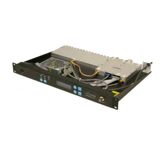
Front Panel Power Assembly Board Supply 16-Way Ground Divider Module Figure 3: Top view of the Base Control Unit (MCU). Expansion Preselector Port Filter here Test Main Alarm Cable Cable Contacts To Station Receivers here here Figure 4: Back view of the Base Control Unit (MCU). Manual 7-9547-1 12/09/14 Page 11... -
Page 12: Figure 5: Functional Block Diagram Of The System
Figure 5: Functional block diagram of the system. Manual 7-9547-1 12/09/14 Page 12... -
Page 13: Initial Power-Up Test
Initial Power-Up Test to insure that they are all properly mated to their associated plugs. To perform the initial power-up test the system should be temporarily interconnected at ground CAUTION: The wide band filter in level using short temporary cables. To temporarily the tower top box is factory tuned interconnect the equipment connect a cable and must not be field adjusted. -
Page 14: Bench Testing
rarily interconnected then power is applied to the 2) To interconnect the equipment connect a cable system by plugging the control unit’s AC cord into a between the main port on the tower box and the suitable AC outlet or by connecting the DC power main port on the base unit. -
Page 15: Figure 7: Display Menu Selections
434B-83H-01-X Menu System 434B-83H-01-X DEFAULT KEY TO BUTTONS KEY TO BUTTONS DISPLAY TX RX SYSTEMS INC CANCEL UP-ARROW ENTER DOWN-ARROW LNA X ACTIVE TURN BYPASS ON XCURRENT XXXmA ENTER TO CONFIRM AS AN EASY REFERENCE RECORD VALUES HERE A CURRENT XXXmA... -
Page 16: Amplifier Termination
Figure 8: Test equipment interconnection for “bench testing” of system components. mode the system will automatically switch back to terminate mode.The system will switch the input of normal operation. the tower top amplifier to the internal load. Note that after 1 minute of being in the terminate mode AMPLIFIER TERMINATION the system will automatically switch back to normal The input of the tower top amplifier can be... -
Page 17: Installing The System
required for installation must be supplied by the To insure stability, it is important to customer. Before mounting the tower top box we fasten the box to the tower using all NOTE recommend that you record the model number and mounting tabs. -
Page 18: Figure 9: System Installation Guidelines
Figure 9: Base Control Unit (MCU) system installation guidelines. Manual 7-9547-1 12/09/14 Page 18... -
Page 19: Figure 10: System Installation Guideline Notes
Figure 10: System installation guideline notes. Manual 7-9547-1 12/09/14 Page 19... -
Page 20: Interference And Im Considerations
9.000 8.000 .500 1.000 7.000 9.063 4X O .515 6.005 Figure 11: Tower top box mechanical details. Interference and IM Considerations 2) Connect the base control unit ground lug to the Equipment Rack Master Ground Bar with a pig- Although Bird Technologies TTA systems are tail. -
Page 21: Feedline Data
Figure 12: Application of rubber splicing tape. NOTE: Additional waterproofing protection can be realized by covering the rubber tape with either “Scotch Kote” or Vinyl plastic Electrical tape (“Scotch” brand 33+). nals are present, making them more prone to inter- storage register works in a forward loop fashion, modulation or carrier desensitization problems. -
Page 22: Attenuation Settings
Alarm Terminals Figure 13: Alarm terminals. Normally open and normally closed terminals are available. TTA NET. The second amplifier, located on the maintain maximum protection of the receivers, base control unit is used to overcome the losses while obtaining the best sensitivity possible. associated with distribution. -
Page 23: Spectrum Analysis
2) With the ATTENUATORS menu displayed press A d d i t i o n a l a t t e n u a t i o n m ay b e the ENTER button to step down to the TTA NET required in cases where carriers are NOTE Gain or DISTRIBUTION sub-menu. -
Page 24: Figure 14: Testing The Output Spectrum
Figure 14: Testing the output spectrum of the system. Maximum Signal Level Mask Receive Band Less than -35 dBm Transmit Band Less than -55 dBm Remaining Spectrum Less than -75 dBm Receive Band Transmit Band Frequency (MHz) Figure 15: Maximum permissible signal levels of receiver outputs of the base unit. Manual 7-9547-1 12/09/14 Page 24... -
Page 25: Operational Tests (Sensitivity And Degradation)
If the level of a transmitter is above -55 dBm the the Effective sensitivity measurement includes site preselector is not adequately performing its job noise. The difference between the two is the sys- and must be changed. tem degradation. 3) All Other Frequencies - The receiver is Front Panel Test Port designed to monitor very low signals and there The front panel BNC test port is connected to the... -
Page 26: Figure 16: Using The Test Port To Measure Sensitivity
1) The signal generator should be connected to interrupted and on-air signals will not be passed the front panel test port. to the station receivers. 2) Be sure the signal generator is setup for a 3 5) Adjust the signal strength from the signal gener- KHz deviation with a 1000 Hz tone (analog) or ator until the 12 dB SINAD or 5% BER point is proper pattern for BER testing. -
Page 27: Effective System Sensitivity
If left unattended, after about 1 minute the antenna connected to the amplifiers perform the input of the active amplifier will the following steps; NOTE automatically switch back to the antenna and on-air signals will again 1) The signal generator should be connected to pass through to the station receivers. -
Page 28: Routine Operation
for future reference. Degradation levels in excess using the ARROW buttons to scroll down from the of 1 to 2 dB should be investigated, as this will default display. The A and B tower top amplifiers decrease the range and performance of the sys- current draw are shown on one menu display and tem. -
Page 29: Alarms
When power is applied to the base control unit the fault lies with one of the tower top amplifiers. There CPU will energize the relay and the common termi- is no switching provision for the amplifier in the nal will then be connected to the normally closed base control unit. -
Page 30: Hardware Problems
Loss of Sensitivity (Intermittent / Continuous) Individual Receive Channel(s) affected All Receive Channels affected Intermittent Continuous Intermittent Continuous Measure Sensitivity Measure Sensitivity Measure Sensitivity Measure Sensitivity Small to moderate loss of Small to severe loss of Small to moderate loss of Small to severe loss of sensitivity sensitivity... -
Page 31: Periodic Maintenance
PERIODIC MAINTENANCE RECOMMENDED SPARE PARTS The following procedures can be followed as part There are no recommended spare parts for the of a periodic maintenance program. TTA system. OPTIONAL EQUIPMENT 1) Bird Technologies recommends that tests for establishing the performance level of the sys- Optional equipment can be purchased from Bird tem, as outlined in this manual, be performed Technologies in order to increase the performance... -
Page 32: Narrowband Filter
mounted in the same rack just beneath the base unit. The optional multicoupler expansion deck will require 1 “rack unit” of space. Narrowband Filter There are a total of nine different narrowband filters available for use with your TTA system. There are four filters that operate in the 792 to 806 MHz range and five filters in the 806 to 824 MHz range. -
Page 33: Snmp Notifications
2) Install the optional filter into the rack or cabinet need to be connected to the internet by the cus- with the four mounting screws contained in the tomer using a standard CAT-5 cable. The SNMP hardware packet (part# 3-16509) which is feature will be energized and active whenever the included with your shipment. -
Page 34: User Administration
Figure 21: The User Administration menu page. additional menu items include network configura- “admin”. Once the correct user name and pass- tion, SNMP configuration, and User Administration. word are entered then a menu box for creating a new user will be presented as shown in Figure 22. When viewing these additional menu listings you will be able to view the screen but you will not be To create a new user enter the new user name and... -
Page 35: Snmp Configuration
Figure 23: Network Configuration menu without password access. modified by clicking in the associated box and field must have a value or traps will not be sent), a entering the new value. password for the user name, encryption type, and an encryption passphrase. -
Page 36: Initial Setup
Figure 25: SNMP Configuration menu without password access. Initial Setup is inactive the deck will be using a static IP and When the TTA system is installed the SNMP fea- the user must enter values for IP address, net- ture should be setup for proper communications. mask, and gateway. -
Page 37: Trap Receiver Gui
Figure 27: Trap Receiver GUI interface. Trap Receiver GUI message it must be examined in detail for an inte- The trap receiver software (MIB file) provides a ger value which is imbedded in the message. Dou- GUI interface for the user so that traps sent from ble clicking on the message will allow you to see the TTA deck can be received and displayed for the imbedded details. - Page 38 Integer Description Normal LNA-A active, LNA-B ok, Base Amp ok LNA-A active, LNA-B ok, Base Amp fault LNA-A ok, LNA-B active, Base Amp ok LNA-A ok, LNA-B active, Base Amp fault LNA-A active, LNA-B fault, Base Amp ok LNA-A active, LNA-B fault, Base Amp fault LNA-A fault, LNA-B active, Base Amp ok LNA-A fault, LNA-B active, Base Amp fault Tower fault, Base Amp ok...
-
Page 39: Appendix A: Ethernet Connectivity
APPENDIX A Ethernet Connectivity The LAN connector on the front panel of the deck provides for 10/100 BASE-T Ethernet connection using the TCP-IP or DNS protocol. The control unit LINK LED ACTIVITY LED deck is shipped from the factory with a default (left side) (right side) TCP/IP address of “192.168.1.1”. - Page 40 APPENDIX B Changing Your Service Computers IP Address When you initially direct connect your service com- 5) The “Local Area Connection Status” box will puter to the SNMP Module it will be necessary to open. Single click the “Properties” tab as shown in Figure B4.
- Page 41 Figure B2: Select the “Network Connections” icon. Figure B3: Select the “Local Area Connection” icon. Manual 7-9547-1 12/09/14 Page 41...
- Page 42 Figure B4: Select the “Properties” tab. Figure B5: Make sure the “Internet Protocol (TCP/IP)” choice is highlighted. Then select “OK”. Manual 7-9547-1 12/09/14 Page 42...
- Page 43 Figure B6: Select “Use the Following IP Address”. Figure B7: Enter the new IP address and Subnet mask values. Manual 7-9547-1 12/09/14 Page 43...
- Page 44 8625 Industrial Parkway, Angola, NY 14006 Tel: 716-549-4700 Fax: 716-549-4772 sales@ .com www. .com...
Need help?
Do you have a question about the 434B-83H-01-T and is the answer not in the manual?
Questions and answers