Advertisement
- 1 Items Included in the package
- 2 Names of the Parts
- 3 Installing the camera in the housing
- 4 Pre-checking before Diving
- 5 Using the Housing and Camera after testing passed
- 6 Connecting the Fiber Optic Cable
- 7 Removing and Replacing the housing Lens Port
- 8 AOI UH-EPL10 Expansion Pathway
- 9 Care and Maintenance
- 10 Specifications
- 11 Documents / Resources
Items Included in the package
Please read this general guide prior to using the housing. It will provide an overview of how this product can be used for optimal performance. For additional information, please consult your local dealer or write to info@aoi-uw.com

- UH-EPL10 Housing Body
- Flat Port (AOI FLP-06-GRY)
- Lens Gear (AOI LG-OM-1442EZ)
- Hot Shoe Connector (AOI HSC-01)
- Micro USB Charging Cable
- Vacuum Pump (AOI VP-01)
- Extended Shutter Release Lever
- LCD Monitor Hood
- Spare Main Seal O-ring x 1pc.
- Spare Vacuum Valve Protection Cap O-ring x 1pc.
- Silica Gel (AOI SIGE-3)
- Silicone Grease (AOI SIGR-5)
- Lanyard
- Port Front Cap for M67 Thread (AOI LFC-01)
- Port Rear Cap for PEN Mount (AOI PRC-02)
- O-ring Remover / White Balance Card (AOI ORR-01)
- Lens Cleaning Microfiber Cloth (AOI MC-01)
- AOI Logo Sticker
- General Guide
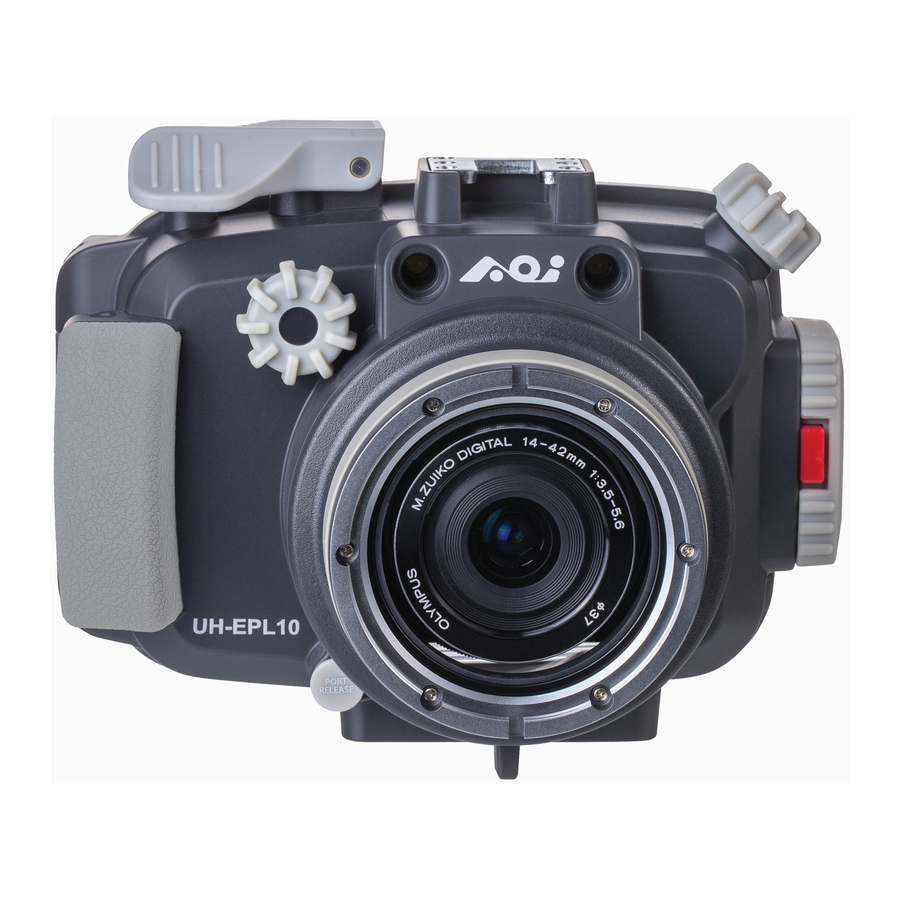
Names of the Parts


- Flat Port (AOI FLP-06-GRY)
- Port Release Button
- Front Housing Body
- Finger Grip
- Mode Dial
- Shutter Release Lever
- Cold Shoe Accessory Mount
- Gear Control Knob
- Fiber Optical Cable Ports
- Flat Port Glass
- Cam Lock
- Cam Lock Release
- Security Lock
- LCD Monitor Hood
- Wet Sensor Strip
- Camera Positioning Bumper
- Multi-control Device
- Signal Indicator
- Micro USB Port
- Power ON/OFF Switch
- Housing Main Seal O-ring
- Rear Cover

- Vacuum Valve
- Mode Dial
![]() Button
Button ![]() Button
Button ![]() Button
Button - Ergonomic Thumb Rest
![]() Button
Button ![]() Button
Button ![]() Button
Button ![]() Arrow Pad/
Arrow Pad/ ![]() Button
Button![]() Arrow Pad/
Arrow Pad/ ![]() Button
Button - OK Button
![]() Arrow Pad/
Arrow Pad/ ![]() Button
Button ![]() Arrow Pad/
Arrow Pad/ ![]() Button
Button ![]() Button
Button![]() Button
Button- 1/4"-20 (x3) Tripod Sockets Plate
- LCD Monitor Window
- LCD Monitor Hood Rails


Installing the camera in the housing
- Before use, ensure that the camera and camera lens are compatible with the housing, lens port and lens gear.

Camera: Olympus PEN E-PL9 or E-PL10
Camera Lens: M.ZUIKO DIGITAL ED 14-42mm F3.5-5.6 EZ
Lens Gear: AOI LG-OM-1442EZ - Before opening the housing Rear Cover, remove the Vacuum Valve Protection Cap by unscrewing it counter-clockwise (fig. i). To equalize the housing internal & external pressure, twist the red colored Vacuum Release Tip counter-clockwise (fig. ii).

- Unlock the Security Lock on the Cam Lock (fig. iii). Press down on the Cam Lock Release and rotate the Cam Lock counter-clockwise at the same time (fig. iv). Rotate the Cam Lock until the Rear Cover is fully separated from the Cam Lock.


- If the Multi-control Device battery power is low, the Signal Indicator will blink rapidly (4 times/sec). Connect the supplied USB Charging Cable to the Micro USB Port on the Multi-control Device and the other end to a USB Charger DC 5V, minimum 0.5A (not supplied). It will take approx. 1.5 hours to fully charge the battery. The table below shows the status of the battery charging and the corresponding light of the Signal Indicator.
- Battery operation time per charge is approx. 3 days (based on 3 dives/day and approx. 250 shots/dive).


Table 1
| Signal Indicator | Indication | Next Action |
| Fast Blinking BLUE light (4 times/sec) | Charge is required | Connect it to a USB charger for charging |
| Fast Blinking GREEN light | Charging in progress | Continue charging |
| Still GREEN light | Charging is completed | Remove from USB charger and stop charging |
- Turn off the camera before installing into the housing. Remove all camera accessories such as Lanyard, Hot Shoe Cover, Lens Filter, and Lens Cap...etc. Push down camera built-in flash, return Camera Monitor back to its original position and make sure the Camera Strap Eyelets are folded down against the camera body (fig. vii). Load the camera into the housing gently and do not hold the camera by the Monitor Screen while inserting.

- If using the Optical Flash Trigger for the external Slave Strobes, the Hot Shoe Connector must be connected between the camera's hot shoe and to the Micro USB Port on the Multi-control Device (fig. viii) and (fig. ix).


- Turn on the power of the Multi-control Device (fig. x).

- Before closing the housing, ensure the camera is positioned properly against the Camera Positioning Bumpers in the front of the housing. Check that the Main Seal O-ring is clean, intact, and properly positioned. There are no obstacles such as the lanyard or strings preventing the secure closure of the housing.
- Clean or replace the Main Seal O-ring if necessary.
- Close the Housing Rear Cover by rotating the Cam Lock clockwise until a "Click" sound is heard (fig. xi). If you encounter resistance, clear obstacles before continuing.
- Switch the Security Lock on the Cam Lock to the "LOCK" position in order to prevent Cam Lock from opening accidentally (fig. xii).

- Once the camera is installed and housing is closed, turn-on the power of the camera and make sure all housing controls and lens gear function properly. Check that the Optical Flash Trigger is functioning with the external slave strobe(s).


Pre-checking before Diving
Perform Vacuum Analyzation
- Power on the Multi-control Device and if the Signal Indicator shows Blinking BLUE (1 time/sec), that means the Vacuum Analyzation and Wet Detection Sensor is on standby mode. Ensure camera is off, close the Rear Cover according to the steps described in "Installing camera into the housing".
- Take off the Protection Cap from the Vacuum Valve and connect the Vacuum Pump onto the Vacuum Valve Tip. Pull and Release the Vacuum Pump handle gently and repeatedly for Vacuum Pumping. During the Vacuum Pumping process, check carefully for changes in color on the Signal Indicator.


- Color Codes Indication:
- Fast Blinking YELLOW
Internal pressure has started to drop. Continue to pump. - Slow Blinking YELLOW
Internal vacuum level is close to the desired value. Slow down pumping. - Still YELLOW
Internal vacuum level has been reached. Stop pumping and the Vacuum Analyzation Process will be started automatically.
Blinking alternate YELLOW & RED
Internal vacuum level is above the desired value. Stop pumping and carefully release air by gently twisting the Vacuum Release Tip counter-clockwise slightly until the Signal Indicator turns to Still YELLOW. If too much air is released into the housing, the Signal Indicator will change back to Blinking YELLOW again. Resume vacuum pumping until Signal Indicator turns to Still YELLOW.
- Fast Blinking YELLOW
- The Vacuum Analyzation Process will start automatically once the Signal Indicator turns Still YELLOW. Disconnect the Vacuum Pump from the Vacuum Valve carefully and then put back Protection Cap to the Vacuum Valve. Do not move or shake the housing or put the housing under the sun when the analyzation process has started.
- The Vacuum Analyzation Process takes approx.4 minutes. Once the process is completed, the Signal Indicator will turn either RED or GREEN, depending on the result:
- Blinking GREEN – Vacuum Analyzation passed and Housing is ready to go into the water.
- Blinking RED – Vacuum Analyzation failed and inspection for leak is required.
- In case of a significant air leakage detected anytime during/after the Vacuum Analyzation Process, the Signal Indicator will turn Blinking RED.
- Below (Table 2) is the summary of Signal Indicator Color Codes Indication.
Table 2
| Signal Indicator | Indication | Next Action |
| Slow Blinking BLUE (1 time/sec) | Ready for Vacuum analyzation | Vacuum Pumping |
| Blinking YELLOW | Vacuum below desired level | Continue pumping |
| Blinking alternate YELLOW - RED | Vacuum above desired level | Twist the Vacuum Release Tip counter-clockwise |
| Still YELLOW | Vacuum analyzation in progress | Wait for 4 minutes for vacuum analyzation |
| Slow Blinking GREEN | Vacuum analyzation test has Passed | Ready for going into water |
| Blinking RED | Vacuum analyzation test has Failed | Inspect the housing for any potential air leakage sources |
| Steady RED with audible alarm | Wet Sensor Strip detects water droplet or moisture | Inspect the housing for any potential water leakage sources |
Perform Water Leakage Test
Once Vacuum Analyzation is completed successfully and Vacuum Valve Protection Cap is secured, review the housing further by checking for water leakage. Submerge it in a shallow tub of water or rinse tank. While submerged, activate all the control buttons, control switches, and control knobs in order to have a dynamic test to prove all the sealed moving parts are water sealed properly. If there is no water droplet observed inside the housing after Underwater Dynamic Test, it means the housing is fully watertight. If water leaks into the housing, the water droplets will be detected by the Wet Sensor Strip located in the lowest part of the housing. Signal Indicator will turn Still RED and audible alarm "BEEP-BEEP-BEEP" will be heard.

Using the Housing and Camera after testing passed
- Please ensure that the Vacuum Valve Cap is in place and completely closed.
- When using the housing, make sure that it is properly secured to you and accessories are properly secured to the housing.
- Do not exceed the housing maximum depth rating of 45 meters (148 ft.)
- If the Wet Detection alarm is triggered during use, it means water has entered into the housing. If that happens, try to position the housing lens port facing down and exit the water safely in accordance with diving procedure and regulation. Upon returning to land, remove the camera from the housing. If only a few droplets of seawater entered the housing, thoroughly wipe off the seawater droplets with a moist towel and dry the inside of the housing thoroughly with tissue paper.
- If seawater leaked into the housing and the Multi-control Device is flooded, take out the camera, rinse the housing cavity thoroughly with running fresh water for a few minutes. Then, dry the housing cavity completely and bring it to your local dealer for servicing immediately.
Connecting the Fiber Optic Cable
- The housing is pre-installed with an Optical Flash Trigger in the Multi-control Device. This feature prolongs the camera battery life by not using the built-in camera flash to trigger the external underwater flash or strobe. The housing is equipped with two Fiber Optic Cable Ports and they are compatible with AOI Fiber Optic Cable with SS cable plug or other fiber optic cable brands using the standard Sea & Sea plug.
- Insert one end of the fiber optic cable into the Fiber Optic Cable Port of the housing (fig. xv) and then insert the other end into the fiber optic cable port on the external flash or strobe.

- The flash trigger signal (electrical signals) will be transferred from the camera Hot Shoe to the Multi-control Device through the Hot Shoe Connector (included in the package). The Optical Flash Trigger in the Multi-control Device will convert the electrical flash triggering signal into an optical signal and then will deliver it to the Fiber Optic Cable. The Fiber Optic Cable (not included in package) picks up the optical signal and delivers it to the external flash or strobe.

NOTE:
- The Optical Flash Trigger is only compatible with multi-core fiber optic cables, please ensure that the fiber optic cable used is compatible.
- The Optical Flash Trigger LED is not easily visible when fired as it is not very bright, so it is difficult to check whether or not the LED is being triggered.

Rinse the Fiber Optical Cable Ports with running fresh water after every use, then let it dry naturally. Do not dry inside of the ports with any tool, this may result in scratches and reduce the capacity of the optical signal transfer.
Removing and Replacing the housing Lens Port
- The ultra-compact Flat Port (AOI FLP-06-GRY) comes standard with the housing and it can be removed for cleaning, inspection, and lubrication of the lens port O-rings (AOI POR-02) on it.
- While depressing the Port Release Button, rotate the Lens Ports counter-clockwise until it stops. Remove the Lens Port by pulling it evenly out from the housing body. If the resistance is too great when rotating the Lens Port, the use of an optional tool (sold separately) - Port Remover (AOI PR-01) may be required.

- To install the Port Lens, align the Lens Port Alignment Marks on the Lens Port and the Housing Body and then push the Lens Port completely down into Housing Body. Turn the Lens Port clockwise until a "Click" sound is heard. When the Port Release Button is no longer depressed, the Lens Port is properly installed and locked.


AOI UH-EPL10 Expansion Pathway
- The UH-EPL10 is designed to grow and expand with your needs and skills. Whether you attach a wet lens (wide-angle conversion lens or close-up lens) directly onto the front of the lens port or the use of dedicated camera lenses (Wide-angle Lens, Fisheye Lens or Macro Lens) on the camera. We have a wide range of compatible Olympus camera lenses, AOI Lens Ports and AOI Wet Lenses to meet even the most demanding of underwater photographers.
- Below is an example of the possible expansion path for AOI UH-EPL10.

* For more information on other products and accessories, visit www.aoi-uw.com or consult with your local dealer.
Care and Maintenance
- Rinse the housing exterior thoroughly with running fresh water after every use. Depress buttons and rotate knobs/dials repeatedly in fresh water to eliminate trapped salt water or debris. Dry the housing and Lens Port with a soft, clean cloth to avoid water spotting and damage.
- To clean the Lens Port Glass, use a mild soap solution or lens cleaner. Do not rinse the inside of port glass. Do not use alcohol or window cleaner on the Lens Port Glass.
- In order to better inspect, position, clean or lubricate the Housing Main Seal O-ring or Lens Port O-rings, carefully remove the required O-ring by using the provided AOI O-Ring Remover/White Balance Card.
- Clean the O-ring and the O-ring groove by using a microfiber cloth only. Use AOI O-Ring Remover/White Balance Card to clean the O-Ring groove. Do not use cleaning substances other than fresh water. Remove sand, dirt, hair or fibers that can prevent a proper housing seal.
- To lubricate O-rings, apply a small amount of silcone grease (AOI SIGR-5) on your fingertips, gently pull the O-ring through the fingertips. This will lightly coat the entire O-ring with silicone grease. Only use the AOI Silicone Grease supplied or those approved by AOI. Using other brands of silicone grease may damage the O-ring. Do not over stretch the O-ring.
- Do not leave the camera and housing in direct sunlight for prolonged periods. Heat may damage the camera and housing.
- Dry well and remove the camera prior to travel and storage.
- Store the housing in a cool and dry place.
Wipe the housing dry and keep water away prior to opening the housing. Do not allow water to be in contact with the interior of the housing. This will cause irreparable damage to the Vacuum Analyzation and Wet Detection System and other electronic/electrical components!
Specifications
| Model Number | AOI UH-EPL10 | |
| Housing Color | AOI UH-EPL10-WHT | AOI UH-EPL10-GRY |
| White | Grey | |
| Compatible Camera Models | Olympus PEN E-PL9 or E-PL10 with kit lens M.ZUIKO DIGITAL ED 14-42mm F3.5-5.6 EZ | |
| Waterproof | 45 Meters (148 ft.) | |
| Main Material | Housing Body: Polycarbonate | |
| Flat Port Glass: Optical Glass with double sided multi-layer AR coating | ||
| Operating Environment | Operation: 0 C ~ 40 C (32 F ~ 104 F) | |
| Storage: -20 C ~ 60 C (-4 F ~ 140 F) | ||
| Battery | Built-in Rechargeable Lithium Polymer Battery (3.7V) | |
| Charging: USB Charger DC 5V, 0.5A (not included) Approx. 1.5 hours for a fully charge | ||
| Battery Operation Time: Approx. 3 days (based on 3 dives/day and approx. 250 shots/dive) | ||
| Dimensions | Approx. 166mm (W) x 128mm (H) x 135.5mm (D) | |
| Weight | On Land: Approx. 734g (LCD Monitor Hood and Lanyard included, camera and accessories not included) | |
| Underwater: Approx. 26g (LCD Monitor Hood, Lanyard, camera, kit lens, batteries, media card and lens gear included) | ||
AOI is a registered trademark of AOI Ltd. All rights reserved.
All other trademarks are the property of their respective owners.

www.aoi-uw.com
Made in China

Documents / ResourcesDownload manual
Here you can download full pdf version of manual, it may contain additional safety instructions, warranty information, FCC rules, etc.
Advertisement

Need help?
Do you have a question about the UH-EPL10 and is the answer not in the manual?
Questions and answers