Advertisement
Overview


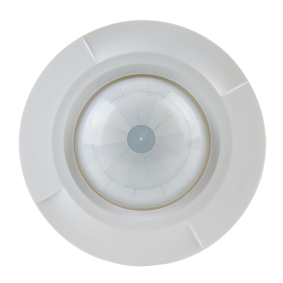
| PRESENCE AND LIGHT SENSOR 2 CHANNELS | |
| h | A |
| 2.5 m | ø 24 m |
Product and application description
PD02X02CON is a presence and light sensor with 2 channels: channel 1 (LOAD is for 230V lamps; channel 2 (LOAD II) is a dry contact useful to interface home and automation bus systems (KNX); for channel 2 LUX is invalid, connection terminals are C1-C2.
Technical Data
Power Supply:
Rated voltage: 220V-240V ±10% 50/60Hz
Load
Load 1 (LS) for Lighting
Incandescent: 2000W
High voltage Halogen: 1000W
Low voltage Halogen: 1000VA
Fluorescent: 750VA
Energy saving or LED lamp: 600VA
Load 2 (C1, C2) for HVAC (Dry contact)
Max. 5A for 12-250VAC (cosФ=1) or Max. 5a for 5-30VDC
Environmental Protection: IP20
Operating Temperature: -20°C ~ 45°C
Dimension
Detection Range: approx. Ф24m/360° at height of 2.5m
Operation & function
Time Adjustment
Time 1 (for LS) with 7 steps adjustable: Short Pulse-30S-1M-5M-15M-30M-OFF Time 2 (for C1, C2) with 7 steps adjustable: 10S-1M-5M-10M-20M-30M-60M
Sens Adjustment
sens with 11 steps adjustable: - sens ~ + sens
The sensor LED indicator will flash 3 times every time the VR knob in adjusted and the desired step is successfully selected
Lux Adjustment
With 7 steps a adjustable (for Load 1 only): 10 - 100 - 500 - 1000 - 2000 lux-Daylight (![]() ) -Teach in(
) -Teach in(![]() )
)
Load 2 is independent and not controlled by Lux settting.
The sensor LED indicator will flash 3 times every time VR knob in adjusted and the desired step is successfully selected.
Short Pulse Function
For staircase timer switch operation: for each detection the load will switch on for 1 sec and off for 9 sec ad a complete cycle before next detection.
Presence Function
During the delay time after the sensor was triggered, the presence function will force the sensor to switch off the load when the ambient brightness is higher than the lux setting value for 5 min. regardless of any movement detected.
Teach in Function
Switch the lux setting to Teach-in-mode at the desired ambient brightness level. The load will turn OFF. The sensor LED indicator will flash for 20 sec while sensor learning the ambient brightness. The sensor LED indicator and the load will stay ON for 3 sec and then go OFF, then the learning process is done. The learned brightness value is accepted as the new brightness switching value.
Trouble Shooting
- Unit will not function at all/Lights won't turn on
- Check wiring to make sure that you have correct AC power at the unit.
- Check the wiring from the unit to the source of power to make sure you have wired the unit correctly.
- Check the ambient light control to see if it was set at your desider level.
- Check if the knob TIME 1 is in OFF position.
-
Detector clicks but does not work
- Check in lamps are broken.
- Check if lamps are tight in lampholders.
-
Lights go on and off quickly
- Ensure light and heat are not being reflectedonto the detector. Check for white or reflective surfaces that may be causing the problem.
- Note the detector is more sensitive in cold weather.
- Make sure the sensor is not installed close to air-conditioner.
- Make sure the Time setting is not at Pulse Mode position.
- Make sure the Lux setting is not at Test Mode position.
-
Lights stay on
- Light bulb sockets may be wired directly to the power source - Recheck the wiring diagram.
- Adjust time to minimum, and ensure unit is firmly fixed to a solid object with no moving branches etc. in field of view.
- Ensure detector is not being activated by stay moving heat sources such as heating outlets.
-
Detector goes on under windy and rainy condition
- Adverse weather conditions and temperature changes can result in unwanted activations.
- This cane be minimized by mounting in a protected location.
-
Maintenance and repair
- Do not attempt to repair as this could invalidate warranty or result in personal injury.
- Clean detector lens and outside casing with damp cloth.
Normal wiring connection


Operation & function
Push-button Function
An external push button is required for wiring with the sensor. Short press the button once to turn on the load, delay time according to TIME setting; short press it again to turn it off, delay time (for OFF) according to TIME setting.
- For staircase timer switch operation.
- Ceiling flush mount with spring clips
- To install the detector, please drill a hole with diameter of 68 mm on ceiling board and keep the power cable outside. Please strip off 6-8 mm of cable sheathing for wiring (see fig.
![]() )
) - Please refer to illustration of fig.
![]() for correct installation, and fix the flush mount spring clips to the detector with 2 pcs retaining screws (see fig.
for correct installation, and fix the flush mount spring clips to the detector with 2 pcs retaining screws (see fig. ![]() )
) - Please refer to illustration of fig.
![]() or correct wiring, and then tighten the flush mount spring clips with 2 pcs non-dropping screws (see fig.
or correct wiring, and then tighten the flush mount spring clips with 2 pcs non-dropping screws (see fig. ![]() ).
). - Raise the two spring clips, and insert the detector into the drilled hole on ceiling (see fig.
![]() )
) - Restore the power supply
- To install the detector, please drill a hole with diameter of 68 mm on ceiling board and keep the power cable outside. Please strip off 6-8 mm of cable sheathing for wiring (see fig.
 )
) for correct installation, and fix the flush mount spring clips to the detector with 2 pcs retaining screws (see fig.
  )
) or correct wiring, and then tighten the flush mount spring clips with 2 pcs non-dropping screws (see fig.
 Usage of Lens Shield
Undesired detection areas can be shielded off by fixing the enclosed lens shield onto the lens. Trim the lens shield with scissors either horizontally or vertically until the desired detection area is obtained (see fig. )
)
NOTE: the lens shield needs to removed with the aid of a tool (see fig.  )
)
Installation & Wiring
The device may be used for permanent indoor installations in dry locations.

- Please disconnect power completely and read the entire instruction manual carefully before installation.
- A circuit breaker (250VAC, 10A) type C according to EN60898-1 of load (CH1) shall be installed in the fixed wiring for protection.
- A circuit breaker (250VAC, 6A) type C according to EN60898-1 of load 2 (CH2) shall be installed in the fixed wiring for protection.
- The device must be mounted and commissioned by an authorized installer.
- The applicable safety and accident prevention regulations must be observed.
- The device must not be opened. Any faulty devices should be returned to manufacturer.
- For planning and construction of electric installations, the relevant guidelines, regulations and standards of the respective country are to be considered.
For further information please visit www.eelectron.com
![]() DISPOSAL
DISPOSAL
The crossed-out bin symbol on the equipment or packaging means the product must not be included with other general waste at the end of its working life. The user must take the worn product to a sorted waste centre, or return it to the retailer when purchasing a new one. An efficient sorted waste collection for the environmentally friendly disposal of the used device, or its subsequent recycling, helps avoid the potential negative effects on the environment and people's health, and encourages the re-use and/or recycling of the construction materials.

eelectron spa
Via Monteverdi 6
I-20025 Legnano (MI) - Italia
Tel: +39 0331 500802 Fax: +39 0331 564826
Email: info@eelectron.com Web: www.eelectron.com


Documents / Resources
References
Download manual
Here you can download full pdf version of manual, it may contain additional safety instructions, warranty information, FCC rules, etc.
Advertisement


Need help?
Do you have a question about the PD02X02CON and is the answer not in the manual?
Questions and answers