Advertisement
DESCRIPTION
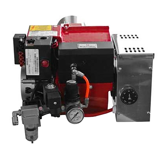
Fig. 1
1.Blast tube
2.Asbestos gasket
3.Flange
4.Body gasket
5. Brake plate
6. Oil n ozzle
7.Heater
8.Rubber
block
9. Transformer
10. Controller
base
11.Motor
2.Photocell
13. Controller
14. Compressor air
15. Reset button
16.Cover
17. Air regulator 1
8. Body screw
19.Oil temperature
20. Seal gas ket
21. Heating tube
22. Limit s of controller
23. Level switch
24. Level height adjust or
25. Oil tank
26.Level switch base
27. Float bal l
28 .Over ow connector
29. Oil tank cover
30. Oil inlet connector
31. Filter
32. Oil pipe 33. Air inlet
1
Advertisement
Table of Contents

Subscribe to Our Youtube Channel
Summary of Contents for BAIRAN STW120
- Page 1 DESCRIPTION Fig. 1 1.Blast tube 2.Asbestos gasket 3.Flange 4.Body gasket 5. Brake plate 6. Oil n ozzle 7.Heater 8.Rubber block 9. Transformer 10. Controller base 11.Motor 2.Photocell 13. Controller 14. Compressor air 15. Reset button 16.Cover 17. Air regulator 1 8.
-
Page 2: Burner Accessories
Outlet-inlet pipe Oil line connector TECHNICAL DATA Item no. Cap . Motor Nozzle Combustion Transfer Power (KW ) (KG ) Motor Supply STW120 -P 10-50 130W 120W 230V/50Hz STW120 12-50 120W 230V/50Hz STW133 -1 40-80 130W 180W 230V/50Hz STW133 -1P... -
Page 3: Overall Dimensions
OVERALL DIMENSIONS Fig. 2 STW120 STW133 STW146 FLANGE DIMENSIONS STW120 STW133 STW146 Fig.3... - Page 4 AIR PUMP STRUCTURE DIAGRAM WARNING: this air pump is no oil pump, is strictly prohibited to add lubricating oil. Fig.4 STW120 AIR PUMP 34. Air inlet 35. Pressure regulator 36.Pressure port 37.Air outlet 39.Coupling Fig.5 STW133 AIR PUMP 1. Pressure regulator 2.
- Page 5 IGNITION ADJUSTION Fig.6 NOZZLE DATA (COMBUSTION ADJUSTMENT)
- Page 6 AIR CONTROLLER (WITHOUT AIR PUMP) 1. Fixed base 2. Air regulating handle 3. Pressure gauge 4. Burner connector (6mm) 5. Solenoid valve 6. Air filter 7. Drainage outlet 8. Air inlet connector (8mm) Fig.7 TRANSFER OIL PUMP Fig.8 40. Oil flow rate adjusting handle 41.
-
Page 7: Burner Installation
BURNER INSTALLATION Warning: the storage oil tank cannot be higher than the burner. Fig.9 1. Accesso ries oil pipe connect with Fig.1 - 30 and Fig.8 - 41. 2. Access ories oil pipe connect with Fig.8 - 43 and connect a ccessories oil lter to Storage oil tank. -
Page 8: Temperature Setting
OIL FLOW CONTROL In order to reduce the frequent start of the transfer oil pump and instant cooling the oil temperature in hea ng oil tank, adjust handle no. 40 in Fig. 8. And control inlet oil rate to get the suitable oil flow rate. (With just over burning oil is better)... -
Page 9: Fault Location
4. Test photocell (bright). 5. A er the normal combus on, oil level in hea ng tank will rise or drop by oa ng ball to control transfer oil pump. FAULT LOCATION 1. Turn on power supply, transfer oil pump cannot work. a. -
Page 10: Wiring Diagram
WIRING DIAGRAM...
Need help?
Do you have a question about the STW120 and is the answer not in the manual?
Questions and answers