Sonifex Redbox RB-DSD8 Handbook
8 channel silence switcher
Hide thumbs
Also See for Redbox RB-DSD8:
- User handbook manual (40 pages) ,
- User handbook manual (136 pages)

Related Manuals for Sonifex Redbox RB-DSD8


Summary of Contents for Sonifex Redbox RB-DSD8
- Page 1 Redbox RB-DSD8 8 Channel Silence Switcher Manufacturers of audio & video products for radio & TV broadcasters...
- Page 2 Information in this document is subject to change without notice and does not represent a commitment on the part of the vendor. Sonifex Ltd shall not be liable for any loss or damage whatsoever arising from the use of information or any error contained in this manual.
-
Page 3: Table Of Contents
Contents Reset to default settings using the reset button Product Warranty - 2 Year Initial Unit Setup Sonifex Warranty & Liability Terms & Conditions 3. Rear Panel DIPSwitch Settings 1. Definitions Rear Panel DIPSwitches: Bank 1 SILENCE LEVEL 2. Warranty... - Page 4 Channel Status Page Miscellaneous Page 7. Webserver Connecting to the device First time usage Bonjour Sonifex Service Discovery App Webserver Password Password set up and logging in Logging out of the webpage Clearing the password 8.Updating The Firmware 9. Technical Specification For RB-DSD8...
- Page 5 Contents & Figures Figures Fig 1-1: RB-DSD8 Front Panel Fig 2-1: RB-DSD8 Status Buttons Fig 2-2: RB-DSD8 Controls & Indicators For Each Channel Fig 2-3: RB-DSD8 Additional Indicators Fig 3-1: RB-DSD8 Rear Panel DIPSwitches Fig 4-1: RB-DSD8 Rear Panel Fig 4-2: Audio & GPI/O Connector Detail Fig 4-3: Audio Connector Pin Numbers Fig 4-4: GPI/O Remotes Connector Pin Numbers Fig 4-5: Communications Connectors...
- Page 6 Warranty Registration Register Online for an Extended 2 Year Warranty As standard, Sonifex products are supplied with a 1 year back to base warranty. If you register the product online, you can increase your product warranty to 2 years and we can also keep you informed of any product design improvements or modifications.
-
Page 7: Product Warranty - 2 Year
Sonifex website within 30 days of purchase, you accordance with the provisions of this Contract. A reference to the consent, can increase your product warranty to 2 years. Go to the Sonifex website at: acknowledgement, authority or agreement of the Company means in http://www.sonifex.co.uk/technical/register/index.asp to apply for your 2... - Page 8 Warranty (vi) the defect has not arisen from a design made, furnished or At the request and expense of the Purchaser the Company will test specified by the Purchaser; the Goods to ascertain performance levels and provide a report of the results of that test.
-
Page 9: Unpacking Your Product
If you require a different power lead, please let us know when ordering the product. Repairs & Returns Please contact Sonifex or your supplier if you have any problems with your Sonifex product. Email technical.support@sonifex.co.uk for the repair/ upgrade/returns procedure, or for support & questions regarding the... - Page 10 T: +44 (0)1933 650 700 • F: +44 (0)1933 650 726 CE Declaration of Conformity and Approval Information This document certifies that the Sonifex product that you have purchased is compliant with CE specifications. If you would like further information on...
-
Page 11: Safety & Installation Of Mains Operated Equipment
Safety & Installation Safety & Installation of Mains Power Cable & Connection Operated Equipment An IEC power connector is supplied with the product which has a moulded plug attached – this is a legal requirement The mains lead is automatically There are no user serviceable parts inside the equipment. -
Page 12: Weee Directive
All products manufactured by Sonifex Ltd have the WEEE directive label Atmosphere placed on the case. Sonifex Ltd will be happy to give you information about local organisations that can reprocess the product when it reaches its “end The units should be installed in an area that is not subject to excessive of use”, or alternatively all products that have reached “end of use”... -
Page 13: Introduction
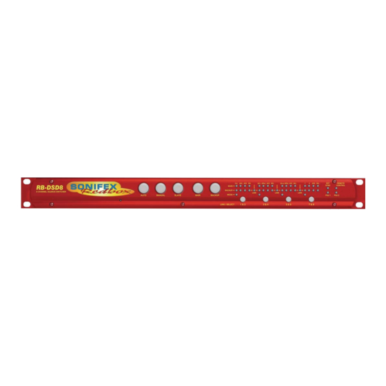
Introduction 1. Introduction Status Buttons Channel Controls & Indicators Reset Button Rear Panel DIPSwitch Indicators Fig 1-1: RB-DSD8 Front Panel The RB-DSD8 8 provides silence detection over 8 channels of audio, Each pair has individual settings and controls but share settings once they organised as 4 pairs. -
Page 14: Clocking & Synchronisation
A powerful feature of the RB-DSD8 is that by using the in-built web server required. or Sonifex SCi serial software, the unit can be programmed for different Auto Lock Mode delay durations, levels and switching functions so that the unit can be set up the unit for any specific application. -
Page 15: Front Panel Controls & Indicators
Front Panel Controls & Indicators 2. Front Panel Controls & Indicators SLAVE Button This button is used to select the unit as slave controlled and is illuminated yellow. Pressing this button disables both the MANUAL button and the AUTO button. Press and hold this button for two seconds to select this mode. -
Page 16: Presence Leds 1(L) 2(R)
Front Panel Controls & Indicators Presence LEDs 1(L) 2(R) illuminates red when the associated output is from the BACKUP input. Only Each stereo input channel has an associated Presence LED which indicates one of these two LEDs can be on for any one channel at any given time. the level of that channel. -
Page 17: Additional Indicators
Front Panel Controls & Indicators Additional Indicators Reset Button In the unlikely event that the RB-DSD8 unit fails to respond, press the reset button to reboot the unit (see Fig 1-1 for location). Reset to default settings using the reset button Press reset and wait for all of the front panel LEDs to illuminate. -
Page 18: Rear Panel Dipswitch Settings
Rear Panel DIPSwitch Settings 3. Rear Panel DIPSwitch Settings The trigger level DIPSwitches adjust the level below which silence detection occurs. This level may be varied from -27dBFS to -84dBFS in 3db steps by raising different combinations (to ON). Please note the range changes depending on the full scale settings. -
Page 19: External Synchronisation Source (Dipswitch 4, Bank 2)
Rear Panel DIPSwitch Settings Remote Start Mode Switch (DIPSwitch 7, Bank 2) Sample Rate DIPSwitch 1 DIPSwitch 2 DIPSwitch 3 This defines whether the remote start switch is momentary or latched. (kHz) Used for starting external equipment when silence is detected on channel 1. -
Page 20: Output Pair Configuration (Dipswitches 9-12, Bank 2)
Remote Control Enable (DIPSwitch 9, Bank 3) These DIPSwitches allow you select whether each output pair is analogue or This DIPSwitch enables serial/ethernet settings which are determined by digital. Set each DIPSwitch so that: the Sonifex SCi software. DIPSwitch 9 - 12 Description DIPSwitch 9 Description When on, the pair outputs a balanced analogue signal. -
Page 21: Rb-Dsd8 Rear Panel Connections
Rear Panel Connections 4. RB-DSD8 Rear Panel Connections To Slave RB-DSD8 Main Audio Audio Power Supply DIPSwitches Inputs Outputs Connection Backup Audio GPIO Ethernet Wordclock Fuse Fuse Inputs Connection Fig 4-1: RB-DSD8 Rear Panel Audio Connections There are 4 x 25-pin female D-type connectors which provide the audio inputs/outputs and the general purpose inputs/outputs (GPI/O). -
Page 22: Gpi/O Remotes Connector
Rear Panel Connections The leftmost two D-types provide for the simultaneous connection of up Analogue Input 3 L- or Analogue Output 3 L- or to four stereo, (eight mono) analogue or digital audio inputs for both Digital Input 3- Digital Output 3- Main and Backup sources. -
Page 23: Alarm Output Pins
Rear Panel Connections Signal Description Signal Description Number Number Channel 1 & 2 MAIN Internal Open Collector to Digital Select BACKUP Diode Protected Input to Ground channel 7 & 8 Microprocessor Channel 3 & 4 MAIN Internal Open Collector to Digital Select MAIN Channel Diode Protected Input to Ground... -
Page 24: Override Time Pin
Pin 6: Receive data- is recommended. The override time can be changed via the Sonifex SCi Pin 5: Ground software. Pin 13 is a voltage supply pin. 5V is supplied up to a maximum All other pins are unused. -
Page 25: Remote Control
CD. The unit can also connect via the Ethernet port using a standard 0x40– Backup Left Channel Green LED on RJ45 Ethernet cable. Both methods connect to the Sonifex Serial Control 0x80– Backup Left Channel Red LED on c is the AES setting for the current channel set where Interface (SCI) software. - Page 26 Remote Control Command Description Response Command Description Response f represents the disable detection DIPswitches where f is DIS:nn Disable silence detection -ACK: a hex value built from: nn is a hex value built from the sum of: 0x01 – Main left channel detection disabled 0x01 –...
- Page 27 Remote Control Command Description Response Command Description Response LLK:n Fail immediately or delay on loss -ACK: ORT:nnn Override Delay length in seconds where -ACK: of lock where nnn is the number of seconds between 2 and 252 n selects between the two modes STE:n Mono or multiple selection where -ACK:...
-
Page 28: Error Messages
Remote Control Command Description Response SYF:n Synchronisation source select -ACK: n selects which synchronisation source is used where: 0 - Input 1 1 – AES/Wordclock SYM:n Synchronisation mode select -ACK: n selects which synchronisation mode is used where: 0 - Master 1 –... -
Page 29: Sci For Rb-Dsd8
Channel Panels - Click on the panel to select this channel pair. The drop down boxes will display the settings for the selected channel pair. The free of charge Sonifex SCi software allows you to control the RB-DSD8 remotely. The interface has two tabs including a status page and a Each Channel Panel contains: miscellaneous options page. -
Page 30: Channel Status Page
SCi For RB-DSD8 Default Time – The amount of delay time used, in seconds, if all the delay DIPswitches are placed in the OFF position. Override Time – The amount of delay time used, in seconds, if the override pin is held in a latched position on the remote port. Remote Start/Audio Fail –... -
Page 31: Miscellaneous Page
SCi For RB-DSD8 Miscellaneous Page Loss of Lock Failure - if selected the unit treats a loss of lock condition as an immediate failure rather than waiting for the detection time. Network - This displays the current settings and status of the network connection on the unit. -
Page 32: Webserver
WebServer Control 7. Webserver address (eg 192.168.0.100) communicate via a browser by entering http://192.168.0.100 in the address bar of the browser. The webserver on the RB-DSD8 provides a method for the user to inspect or modify its settings. The Ethernet port should be connected to a network To connect via Bonjour Name in a Bonjour enabled device enter the name and then the unit will be accessible to all computers on that network - in the browser address bar. -
Page 33: Bonjour
If bonjour is installed select the Bonjour tab and then the Sonifex Web Server Service to show all devices. Select the device you wish to connect to, by type and serial number, and then launch to connect via a browser. -
Page 34: Updating The Firmware
Successful Update: The AUTO button will be solid green for two seconds Check for updates at: http://www.sonifex.co.uk/technical/software/ and the unit will automatically reset and begin running the new code. Firmware updates can be conducted through either Serial/Ethernet port, Unsuccessful Update: The MANUAL button will be solid red for two via SCi or the webpage. -
Page 35: Technical Specification For Rb-Dsd8
Technical Specification 9. Technical Specification For RB-DSD8 Audio Specification - Digital In To Digital Out Front Panel Indicators Presence LEDs: For all input channels Impedances: word clock input Link LEDs: Show which channels are controlled Dynamic Range: >138dB ref. 0dBFS, 22kHz BW, unity gain concurrently THD+N: <-137dBFS, 0dBFS, 20-20kHz, unity gain, 20kHz BW... - Page 36 Technical Specification Remote Start: Latched or momentary, via DIPswitch Equipment Type Input Lock Loss: Switch immediately or treat as silence delay, RB-DSD8: 8 channel silence switcher via rear panel DIPswitch Digital or Analogue Digital or analogue, via rear panel DIPswitches Physical Specifications Output: Dimensions...
- Page 37 Notes...
- Page 38 Notes...
- Page 39 Notes...
- Page 40 . s o n i f e x . c o . u k t:+44 (0)1933 650 700 f:+44 (0)1933 650 726 sales@sonifex.co.uk...
Need help?
Do you have a question about the Redbox RB-DSD8 and is the answer not in the manual?
Questions and answers