Table of Contents
Advertisement
Quick Links
USER'S MANUAL
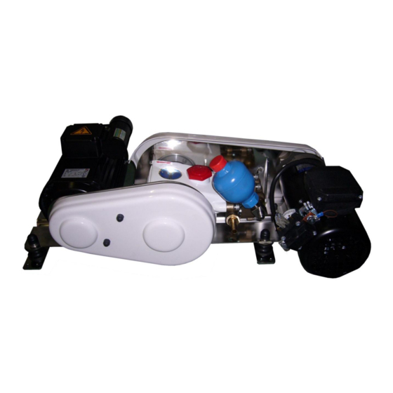
DUO100® AC&DC installation and utilisation
First bi powered water maker world-wide, producing 100 L/Hr,
with automatic rinsing – model patented
DESSALATOR
Technical and Sales Departments :
Z.I des 3 Moulins – « Euro 92 » – Bât. D – rue des Cistes – 06600 ANTIBES
FRANCE
Tel: (33) (0)4 93 95 04 55
Fax: (33) (0)4 93 95 04 66
e-mail:
contact@dessalator.com
Web site:
www.dessalator.com
Version A3
Advertisement
Table of Contents

Related Manuals for DESSALATOR DUO100

Summary of Contents for DESSALATOR DUO100
- Page 1 USER’S MANUAL DUO100® AC&DC installation and utilisation First bi powered water maker world-wide, producing 100 L/Hr, with automatic rinsing – model patented DESSALATOR Technical and Sales Departments : Z.I des 3 Moulins – « Euro 92 » – Bât. D – rue des Cistes – 06600 ANTIBES...
-
Page 2: Table Of Contents
2 Motor unit page 3 Membrane unit page 4 Control panel page 5 3. Starting the Dessalator® page 6 4. Directions for use (membranes) page 7 5. Maintenance: 5.1 Maintaining and 5.2 rinsing the membranes page 8 5.2 Rinsing the membranes page 9 5.3 Sterilizing the membranes... - Page 3 I n s t a l l a t i o n d i a g r a m D e s s a l a t o r D U O 1 0 0 A C & D C B i p o w e r e d : 1 2 o r 2 4 V A N D 1 2 0 V o r 2 3 0 V Production Diam.
-
Page 5: Components
1. Components supplied with the Dessalator®: Version A3 Hull valve: It must be located the lowest possible in the boat, to the back for a motor yacht or in the centre near the keel for a sailing boat. The hull valve strainer filters out the larger particles at system entrance. -
Page 6: Sea Water Inlet
2. How to install the watermaker: 2.1 Sea water inlet Sea water inlet valve The strainer should be positioned as low as possible below the waterline and as far as possible from the deck waste oulet. Drill the hull 21mm. The grooves on the strainer should be facing forward (towards the bow) for maximum water intake when the boat is moving forward. -
Page 7: Motor Unit
35mm² for the 12V or 20mm² for the 24V. The Dessalator control cable is 5m long and is equipped with a plug with a pin locator system. The Dessalator® can only be operated when the power cable is connected to a DC supply. -
Page 8: Membrane Unit
2. How to install the desalinator: 2.4 Membrane unit The membranes can be installed horizontally, preferably flat or on a wall support. They are mounted using 8 Parker screws in stainless steel brackets . As the hose from the HP pump vibrates, it is preferable to install the hose with an insulating tube. -
Page 9: Control Panel
If this is not possible, remember to open the outlet valves before using the Dessalator. Electrical connection: ... - Page 10 3. Starting the DUO: 1. Ensure the valves are open before starting up the watermaker (Hull valve and waste oulet valve if relevant) 2. To be done compulsory: For the first use, after the replacement of the filter, when lifting the boat out of the water or for a long period of not using your water maker, please fill the circuit with fresh water: put the handle valve on the pre filter to the back;...
-
Page 11: Directions For Use (Membranes)
4. Directions for use: MEMBRANES DELICATE COMPONENTS Reverse osmosis membranes must be carefully maintained as they are the most delicate elements of the system. We recommend that the maintenance instructions are carefully followed to prevent the membranes from damage and to ensure the guarantee is not invalidated. Maximum production capacity of the desalinator is achieved with a sea water temperature of 25°C. -
Page 12: Maintenance
5. Maintenance: CAUTION: IN FREEZING CONDITIONS, PLEASE EMPTY THE FLOWMETER TUBE ON THE CONTROL PANEL BY DISCONNECTING THE PRODUCTION HOSE AND BLOWING OR INJECTING AIR INTO THE HOSE, PROTECT YOUR MEMBRANES WITH BLANKETS. 5.1. Maintaining the membrane After 1,000 working hours, it is normal that the flow lowers between 10 and 15%. If more, you should think of replacing the membranes. - Page 13 5. Maintenance: Manual Flush Next to the pre filter there is a valve. The valve is connected to the fresh water system of the boat and turning it, will automatically start the boat’s water pump and a flow of fresh water from the tank to the watermaker.
-
Page 14: Sterilizing The Membranes
5. Maintenance: 5.3. STERILIZING THE MEMBRANE When should the membrane be sterilized? Normally, regular monthly rinsing of the membrane may be all that is required to maintain the membrane. If this is not possible, sterilization will be necessary. A sterilisation procedure should be carried out every six months. -
Page 15: Spare Parts And Accessories
6. SPARE PARTS AND ACCESSORIES Spare parts Dessalator® systems are very reliable, hardwaring and do not generally require expensive services. Nevertheless an accident is always possible (running without enough water, accidental overpressure, impact,…). Should the need arise, we supply spare parts and maintenance accessories: ... -
Page 16: A1: Reverse Osmosis
APPENDIX – A1 REVERSE OSMOSIS What is the reverse osmosis principle used in your desalinating system? Sea water is forced at high pressure through the membranes which act as “molecular sieves”, only allowing pure fresh water to pass through. Most dissolved solid particles will not penetrate the membrane. -
Page 17: A2: How To Assemble The Hp Connectors
APPENDIX – A2 Installation instructions – HP Connectors DESSALATOR 1. Screw the brass union (skirt) anti-clockwise onto the HP pipe, no more than 2.5cm. Stop where the inner threading disappears. 2. Insert the steel tapered end-piece into the stainless steel nut, and tighten very firmly on the male tapered union. -
Page 18: A3: Sterilizing Cartridge - Instructions For Use
APPENDIX – A3 Sterilizing cartridge – instructions for use The desalinator is not running: 1. Close the sea water inlet valve. 2. Open the sterilizing cartridge 3. Remove the top grid 4. Place the foam filter at the bottom of the filter 5. -
Page 19: A4: Manual Rinsing
APPENDIX – A4 Your DESSALATOR® is equipped with an automated rinsing. Please find her below the procedure if you wish to rinse it manually. MANUAL RINSING Your Dessalator® is equipped with an automated rinsing. Here below the procedure to rinse manually. -
Page 20: A5: Troubleshooting
APPENDIX – A5 Troubleshooting PROBLEM CAUSE SOLUTIONS Leak on the pressure Loosened regulation Tighten the cable gland regulator in front of the cable gland with a 12 wrench. control panel - Reduced water inlet - Ensure correct size of or air inlet in the hoses (diameter), clips Noisy HP pump. -
Page 21: A5: Troubleshooting - Led Indicator
APPENDIX – A5 Troubleshooting: led indicator - Page 17 -...
Need help?
Do you have a question about the DUO100 and is the answer not in the manual?
Questions and answers