Advertisement
DOCUMENT PRINT INSTRUCTIONS: REFERENCE SHEET V-SHD1 P/N 77-600023-001 REV 1.0 |
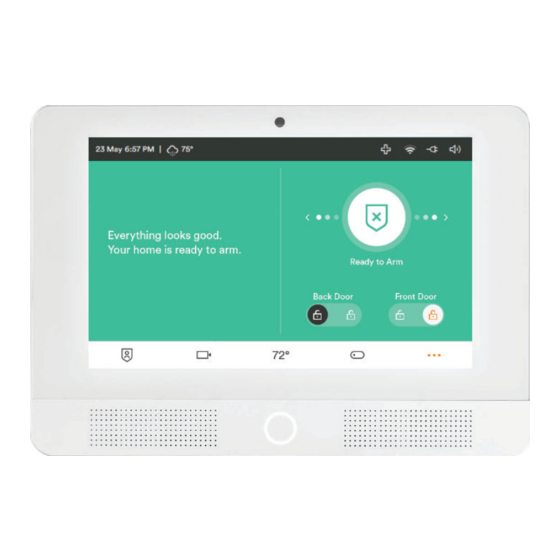
Vivint Glance™ Display
(V-SHD1)
Quick Reference
The Vivint Glance™ Display (V-SHD1) is a touchscreen device that provides secondary access and
control of a Vivint system wherever it's most convenient in the home. The Glance communicates
wirelessly with the primary control panel and replicates its user-interface, allowing the user to
perform all of the same security and automation functions. With a streamlined design, the display
can be installed on a wall or on a desk or table top, in any room, for extended system control.
The Glance has a Home Button for instant navigation to the main screen whose LED light indicates
system status. All of the system's security sensors and smart home devices can be accessed via the
synchronized interface. Emergency features are available through the Emergency icon on the
touchscreen's status bar. Display and sound settings can be configured uniquely for the Glance.
Other features include: microphone and speaker supporting two-way talk with cameras (Ping,
DBC), and backup battery in case of power outage (note: the panel's W-Fi connection will be lost).
This document includes installation instructions, as well as technical specifications and regulatory
declarations. For feature descriptions and usage, direct the customer to the Vivint Support Site.
Installation Instructions
The Glance Display can be installed on a wall or on a flat surface like a desk or table top. For best
results, the Glance should be as near to the control panel as possible for a strong Wi-Fi connection.
IMPORTANT: A maximum of two Glance Displays can be installed per system.
Mounting on the wall:
NOTE: Package contents – display, wall-mount back plate, power supply, mounting screws.
1. Unpack the box, and separate the display's main body from the wall-mount back plate
(loosen the retaining screw, if necessary).
2. Use the back plate to mark the location where you want to install the Glance. Mark the
screw holes and the wiring access hole, and drill the wiring hole. (NOTE: Install near an
unswitched wall outlet. Be careful to not drill through pipes or electrical; and mindful of
distance and obstructions to the control panel in order to ensure a sufficient Wi-Fi signal.)
3. Measure, cut, and route 18 AWG 2 conductor unshielded cable from the outlet to the
mounting location (maximum run: 100 feet), and push the wires into the power terminal
plug on the back plate. You do not need to observe polarity.
4. Attach the back plate to the wall with the provided screws (use the anchors, if necessary).
5. Remove the tape covering the backup battery wire, and insert the battery connector.
6. Place the display on the wall-mount back plate. First, noting the location of the clasps,
push the display unit flush on to the back plate, then slide the display down so that the
clasps hold it securely in place. Tighten the retaining screw on the bottom of the display.
7. At the outlet, connect the wires to the power supply. You do not need to observe polarity.
8. Plug the power supply into the wall outlet.
9. At the primary control panel, add the Glance to the system. See the procedure below.
Desktop-Mount Display (rear) —
Desktop-Mount Display (front) —
Power Supply and Cable —
Adding the Glance Display to the Primary Control Panel Network
Once the Glance is installed and powered on, you must add (pair) it as a wireless device to the primary
control panel (i.e. panel network) via the Installer Toolbox. Follow these steps:
1. At the primary control panel, go to the Installer Toolbox (Menu > Software Version > Installer PIN),
press Zones, Key Fobs, Keypads > Secondary Glance Panels, and then press Add Panel.
2. Select the default wireless connection method, Wi-Fi Connect, and press Add. (NOTE: You can use
the WPS method if Wi-Fi Connect fails. WPS requires that you manually press Connect at the Glance.)
Wall-Mount Back Plate (outside) —
Power Supply and Cable —
Mounting on a desk/table top:
If installing the Glance on a table, counter, or desk top, you must have the desktop-mount back plate
and its accompanying power supply cable (separate accessory kit), and then follow these steps:
1. Determine where to install the display. (NOTE: Install near an unswitched wall outlet.)
2. Separate the display from the wall-mount back plate; and use instead the desktop-mount kit.
3. Remove the clear tape covering the backup battery wire, and insert the battery connector.
4. Place the display on the desk-top back plate. First, noting the location of the clasps, push the
display unit flush on to the back plate, then slide the display down so that the clasps hold it
securely in place. Tighten the retaining screw on the bottom of the display.
5. Route the desktop-mount power supply cable (with its built-in connector) from the outlet to
the mounting location, and plug the barrel connector into the back of the desktop-mount.
6. At the wall outlet, slide the built-in connector (at the other end of the cable) into the space
on the adapter with the screw terminals (screwed down all the way) until it snaps into place.
7. Plug the power supply into the wall outlet.
8. At the primary control panel, add the Glance to the system. See the procedure below.
Primary Control Panel
Wall-Mount Display (front) —
Wi-Fi
Connection
Glance Display
Advertisement
Table of Contents

Subscribe to Our Youtube Channel
Summary of Contents for Vivint Glance Display
- Page 1 Wall-Mount Back Plate (outside) — The Glance Display can be installed on a wall or on a flat surface like a desk or table top. For best results, the Glance should be as near to the control panel as possible for a strong Wi-Fi connection.
- Page 2 • Consulter le revendeur ou un technicien radio / télévision expérimenté pour de l'aide. Contains FCC ID: YVK-BL-LW08-5, IC: 9295A-BL-LW08-5; or FCC ID: 2AE3B-AEH-AR9485, IC: 20662-AEHAR9485; or FCC ID: PPD-AR5B125, IC: 4104A-AR5B125 *For more compliance, warranty, and service information, visit: support.vivint.com © 2017 Vivint Inc. All Rights Reserved. www.vivint.com 1-800-216-5232 Device M/N: CP03...
Need help?
Do you have a question about the Glance Display and is the answer not in the manual?
Questions and answers