Table of Contents
Advertisement
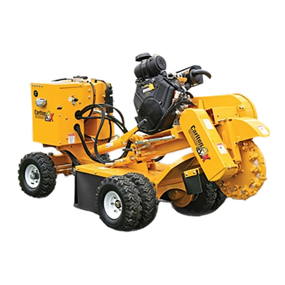
SP5014 SERIES
Machine Serial #
Engine Model & Spec #
Engine Serial #
Purchase Date
Dealer
J.P.Carlton Company
Div. D.A.F. Inc.
121 John Dodd Road
Spartanburg, SC 29303
Ph. (864) 578-9335
Fax (864) 578-0210
www.stumpcutters.com
Owner's Manual
_____________
_____________
_____________
_____________
_____________
REVISION: 220623-1
Advertisement
Chapters
Table of Contents

Related Manuals for Carlton SP5014 Series


Summary of Contents for Carlton SP5014 Series
- Page 1 Owner’s Manual SP5014 SERIES Machine Serial # _____________ Engine Model & Spec # _____________ Engine Serial # _____________ Purchase Date _____________ Dealer _____________ REVISION: 220623-1 J.P.Carlton Company Div. D.A.F. Inc. 121 John Dodd Road Spartanburg, SC 29303 Ph. (864) 578-9335 Fax (864) 578-0210 www.stumpcutters.com...
- Page 3 ENGINE EXHAUST WARNING WARNING This product and the fuels used to operate this product (Gasoline or Diesel), and the products of combustion of such fuels, can expose you to chemicals including benzene, which is known to the State of California to cause cancer, birth defects, or other reproductive harm.
- Page 4 SP5014 SAFETY ALERT...
- Page 5 SP5014 SAFETY ALERT OPERATE MACHINE FROM 25 FEET AWAY. KEEP SPECTATORS AWAY.
- Page 6 SP5014 SAFETY ALERT...
- Page 7 SP5014 SAFETY ALERT...
- Page 8 STUMP GRINDER LIMITED WARRANTY J.P. Carlton Co. Inc., hereafter referred to as the “Manufacturer”, warrants each new Carlton Grinder to be free of defects in workmanship and material for a period of one year. This warranty takes effect upon delivery to the original retail purchaser. The manufacturer, at its option, will replace or repair, at a point designated by the manufacturer, any parts which appear to have been defective in material or workmanship.
- Page 9 The manufacturer will provide replacement parts at no cost to the customer for defective parts during the warranty period. Defective parts must be returned to J.P. Carlton Company. It will be the customers’ responsibility to install the replacement parts unless arrangements are made with the selling dealer.
- Page 10 BLANK SHEET...
- Page 11 Warranty Validation Form Congratulations on your purchase of a Carlton Stump Grinder. This product has been designed and manufactured to provide years of profitable service while minimizing maintenance and downtime. Please take the time now to complete this warranty validation form. This information is necessary for Carlton to instate your warranty.
- Page 12 BLANK SHEET...
-
Page 13: Table Of Contents
SP5014 TABLE OF CONTENTS INTRODUCTION FOREWORD GENERAL INFORMATION MACHINE FEATURES MACHINE SPECIFICATIONS OPERATION SAFETY PRECAUTIONS DAILY CHECKLIST MACHINE CONTROLS TRANSPORTING MACHINE OPERATION MAINTENANCE MACHINE MAINTENANCE TROUBLESHOOTING GUIDE SERVICING CUTTER WHEEL SERVICING HYDRAULICS SERVICING BELTS SERVICING BEARINGS TRACK OPERATION MANUAL APPENDIX A CONTACT INFORMATION BACK... - Page 14 Slowly experiment with the controls and gradually work yourself up to the full capabilities of this machine. The Carlton® Model SP5014 is a durable and profitable professional stump grinder. Read this manual, the engine manual, along with the safety and operational decals on the machine.
-
Page 15: General Information
Any reference made to right, left, front or rear in relationship to the stump cutter is illustrated in the following picture. Please refer to these any time you call your dealer or J. P. Carlton Company for parts or assistance. -
Page 16: Machine Features
SP5014 MACHINE FEATURES Gas Power Heavy construction Carbide tipped cutter teeth: Standard Cutter Optional Wireless remote Premium tires on the Wheel 32 teeth, Optional control wheel version with a Razor Wheel 48 teeth four-wheel stance ... -
Page 17: Machine Specifications
SP5014 MACHINE SPECIFICATIONS MODEL SP5014 WHEEL Approximate Dimensions & Weights (Dimensions & weights will vary depending on optional equipment) *Approx. Weight: 2300lbs. (1043.26 kg) Overall Dimension: Length:117.5” (298.45 cm) **Width: 35.75” (90.81 cm) Height: 61.25” (155.58 cm) Cutting Depth: 12.75” (32.39 cm) Cutting Height: 25”... - Page 18 SP5014 MACHINE SPECIFICATIONS MODEL SP5014 TRACK Approximate Dimensions & Weights (Dimensions & weights will vary depending on optional equipment) *Approx. Weight: 2700 lbs. (224.70 kg) Overall Dimension: Length: 96” (243.84 cm) **Width: 29.5” (74.93 cm) Height: 63” (160 cm) Cutting Depth: 12”...
- Page 19 SP5014 SAFETY PRECAUTIONS Before operating the stump cutter, read this manual, the engine manual, and all the safety decals on the machine. Know all parts of the machine and their functions, especially the shut down procedures in case of emergency. No inexperienced person may operate machine.
- Page 20 (i.e. clearing rocks, wood chips, etc.). DO NOT modify or change any part without written approval from J. P. Carlton Company. DO NOT ride, sit, stand, lay, or climb anywhere on this machine during operation, while running, or during transport.
- Page 21 Keep cutter wheel skirt guards in good condition to help control chips during grinding. Keep safety and instructional decals clean and replace any that are damaged, difficult to read, or missing. Decals may be purchased from J.P. Carlton or an authorized dealer.
- Page 22 SP5014 SAFETY PRECAUTIONS This machine can tip over sideways if operated on non-level surface. This can cause serious injury to operator and machine. Avoid steep side inclines when operating this machine! The narrow design width required for operating this model machine in tight confines, makes it susceptible to tipping over sideways.
- Page 23 SP5014 DAILY CHECKLIST DAILY CHECKS SHOULD BE PERFORMED BEFORE STARTING ENGINE FOR THE DAY. DO NOT INSERT KEY INTO ENGINE UNTIL ALL CHECKS HAVE BEEN COMPLETED. Check engine oil at dipstick. Engine must be level. Boom in raised position will not affect the engine position;...
- Page 24 SP5014 MACHINE CONTROLS HYDRAULIC CONTROLS Your wheel or track machine has a series of hydraulic controls located on the machine control panel and radio transmitter, which are clearly marked for use. To operate, push levers/toggle switches in the direction of the command you want to perform. See illustrations (right) and details below.
- Page 25 SP5014 MACHINE CONTROLS HYDRAULIC CONTROLS -WHEEL (cont.) GEAR (HIGH/ LOW) (Same on Remote) This switch is on the side of the control panel and on the remote. (Note: to control the gear selection functionality with the wireless remote, the gear switch on the machine control panel must be in the HIGH position.) The switch controls the drive motors and determines how fast the...
- Page 26 SP5014 MACHINE CONTROLS HYDRAULIC CONTROLS (cont.) TRACK MACHINE: RIGHT TRACK (FWD/REV) (Shown as R. TRACK-FORWARD / REVERSE on Remote.) This switch operates only the right track drive motor. LEFT TRACK (FWD/REV) (Shown as L. TRACK-FORWARD / REVERSE on Remote.) This switch operates only the left track drive motor.
- Page 27 SP5014 MACHINE CONTROLS HYDRAULIC CONTROLS -TRACK (cont.) BLADE (UP/DOWN) (Note: may be labeled as TONGUE on Remote). This switch raises and lowers the push blade at the front of the machine. TRACK WIDTH (OUT/IN) (Shown as TRACKS-IN/OUT on Remote.) Use this switch to extend the track width for more stability in positioning and during grinding or to retract the track width for...
- Page 28 SP5014 MACHINE CONTROLS HYDRAULIC CONTROLS -TRACK (cont.) FLOW (HIGH/ LOW) (Only on Remote) Flow control affects how fast the machine travels. High flow is for moving the machine from one place to another very quickly. Low flow is used for more precision in tight places or when positioning the cutter wheel close to the stump.
- Page 29 SP5014 MACHINE CONTROLS PROGRAMMING OMNEX WIRELESS REMOTE If there is a problem with the receiver or the transmitter and either must be replaced, you will need to program the new unit to communicate with the existing unit. Or if you have more than one transmitter for this machine, it will need to be programmed to communicate with the existing receiver.
- Page 30 SP5014 MACHINE CONTROLS PROGRAMMING HATOX WIRELESS REMOTE To pair the handheld transmitter and the machine receiver, follow the below steps. Stand within 3 feet of the machine receiver with no obstruction between the two devices. Activate the transmitter into pairing mode by holding the Cutter Head Left/Right switch in the LEFT position and the Cutter Head Down/Up switch in the UP position then...
- Page 31 SP5014 MACHINE CONTROLS ENGINE CONTROLS *Refer to the engine manufacturer’s manual for controls, operation, and service. If the machine is equipped with the optional wireless remote system, it will have an On/Off toggle switch and engine ignition key switch for startup and shutdown of the engine. The On/Off toggle switch is located on the machine control box and must be switched to the On position before engine will start.
- Page 32 SP5014 TRANSPORTING CAUTION DO NOT TOW! This machine is designed to be transported to the job site and will move under its own power once on site. Transport machine in a suitable vehicle designed for a load of these dimensions and weight. A low trailer is recommended due to its decreased entry height and will be safer all around.
- Page 33 SP5014 TRANSPORTING WARNING Trailer must be securely attached to tow vehicle before loading or unloading the stump grinder. Do not unload on anything other than level ground! LOADING • Start engine as recommended by the engine manufacturers manual. • Increase engine RPM, raise cutter head just off the ground.
-
Page 34: Daily Checklist
SP5014 MACHINE OPERATION STARTING PROCEDURE *Read this Manual, All Machine Decals, and the Engine Manual Before Starting. Check all fluids before starting. Drive belts (cutter wheel) must be disengaged before starting. Inspect all connections, teeth, tires, etc. (See Daily Checklist). CAUTION Do Not operate the engine at an angle greater than 25°... - Page 35 SP5014 MACHINE OPERATION WIRELESS REMOTE (con’t) On the OMNEX transmitter, press the E-STOP button down. Toggle any switch on the transmitter. Twist the E-STOP button clockwise to release. (Note: Release the E-STOP button within 10 seconds to power up the transmitter or the unit will power down.) When the transmitter is operating there is a yellow ACTIVE light that will be...
-
Page 36: Machine Operation
SP5014 MACHINE OPERATION START ENGINE Start engine. Turn the ignition key THROTTLE switch clockwise one stop (On position) KEY SWITCH to turn the electrical system on. The key should remain in the on position while the engine is running. Turn the key fully clockwise (Start position) this will start CHOKE the engine. - Page 37 SP5014 MACHINE OPERATION DANGER Engaging or Disengaging Cutter Wheel at High Engine Speed Can Cause Personal Injury and Machine Damage. Always Disengage Before Turning Machine On/Off. Reduce engine speed to idle. (Approximately 1000-1200 RPM) Raise cutter wheel clear of stump. ...
- Page 38 SP5014 MACHINE OPERATION Lower spinning cutter wheel to stump and make a few light passes at stump to get a feel for the cutting action. Gradually increase cutting action and work away at stump by swinging cutter wheel left- to-right-to-left through stump in a sideways motion.
- Page 39 SP5014 MACHINE OPERATION POSITIONING MACHINE The SP5014 Wheel machine has features that provide optimal stability during normal operation and positioning. For your safety and for the protection of your machine, follow these guidelines. The wheel machine comes equipped with dual rear wheels for stabilization when maneuvering around the work area and operating the boom when cutting.
- Page 40 SP5014 MACHINE MAINTENANCE DANGER More accidents occur while performing maintenance than any other time! Use extra caution!! DO NOT PERFORM MAINTENANCE OF ANY KIND ON THIS MACHINE UNLESS: The engine is turned off. The ignition key has been removed. ...
- Page 41 SP5014 MACHINE MAINTENANCE Check cutter wheel, pockets, and teeth for wear (Daily). If any repair is needed, see Servicing Cutter Wheel section for further instructions. DO NOT OPERATE STUMP CUTTER WITHOUT A COMPLETE SET OF TEETH. Check setscrews in jackshaft bearings for tightness (Weekly).
- Page 42 SP5014 MACHINE MAINTENANCE BELTS Check belt tension (Daily). Inspect for wear and alignment (Monthly). For details on replacing belts, see Servicing Belts section of this manual. NOTICE Tension on newly installed belts drops rapidly during the first hours of operation. Check and adjust frequently during the first 24 hours.
- Page 43 SP5014 MACHINE MAINTENANCE CHECK FOR WEAR Inspect belts, sheaves and/or sprockets for wear. See illustrations to assist with inspection. For details on replacing belts, see Servicing Belts section of this manual. V-Belt-drive efficiency depends on full contact between the belt and the sheave walls.
-
Page 44: Machine Maintenance
SP5014 MACHINE MAINTENANCE BELT TENSION ADJUSTMENT NOTICE Inspect and/or repair the following before continuing with setting belt tension: Grease and oil on the belt: Grease and oil on a belt will cause rapid deterioration. Clean oil and grease from the sheaves, wipe the belt with a clean cloth. ... - Page 45 SP5014 MACHINE MAINTENANCE BELT TENSION ADJUSTMENT (cont.) Procedure for Cutter Poly Chain Belt: There are jam bolts, FRONT (cutter side) Rear Jam and REAR (engine side), on each side of the Bolt jackshaft which are used to slide the jackshaft bearing and shaft.
- Page 46 SP5014 MACHINE MAINTENANCE LUBRICATION CHART Use NLGI Grade 2 grease or equivalent. Always clean tip of grease gun fitting and grease fitting on machine before attaching hose to prevent dirt from being forced into machine parts. Note: Wipe off excess grease. Excess grease will attract dirt.
- Page 47 SP5014 MACHINE MAINTENANCE...
- Page 48 SP5014 TROUBLSHOOTING GUIDE COMPLAINT CAUSE CORRECTION Engine will not start. On/Off switch on machine Move switch to the ON (See Engine Manufacturers’ control panel is in off position. position and follow normal Manual for further startup procedure. information.) ...
- Page 49 SP5014 TROUBLSHOOTING GUIDE COMPLAINT CAUSE CORRECTION Cutter wheel stops turning. Belt not engaged. Adjust yoke assembly. Belt loose. Tighten belt. Engine belt broke. Replace belt. Poly Chain® belt broken. Replace belt. Sheared key in shaft. ...
- Page 50 SP5014 SERVICING CUTTER WHEEL DANGER More accidents occur while performing maintenance than any other time! Use extra caution!! DO NOT PERFORM MAINTENANCE OF ANY KIND ON THIS MACHINE UNLESS: The engine is turned off. The ignition key has been removed. ...
-
Page 51: Servicing Cutter Wheel
SP5014 SERVICING CUTTER WHEEL TOOTH ARRANGEMENT Inspect pockets, teeth, and bolts for damage Use anti-seize on threads to prevent bolts and replace as required. from “freezing up” in cutter wheel pockets. When replacing pockets, always replace When replacing complete set of teeth, be new pockets across from each other in sure to duplicate original factory tooth order to prevent vibration. - Page 52 SP5014 SERVICING CUTTER WHEEL OPTIONAL: Razor Cutter Wheel If the machine is supplied with the optional Razor cutter wheel, there are 36 teeth to a complete set. There are 12 outer Short Plow Bolt with Long Head Bits and 24 side Plow Bolt Bits. CAUTION Do not operate machine without a full set of teeth.
- Page 53 NOTE TOOTH PLACEMENT IN EACH POCKET ROTATION LEFT SIDE CARLTON SP4012 TRIUMPTH MANUAL Note: It may be necessary to use a 1 1/4” hole saw to remove debris around nut to make tooth removal easier.
- Page 54 SP5014 SERVICING CUTTER WHEEL TOOTH SHARPENING Begin by chamfering shank back past edge of carbide. You do this because if it is not back far enough the shank will hit the stump instead of the carbide, thus causing a lot of vibration.
- Page 55 10 hours of operation. After that, at 200 hours increments. Replace with the same type of in-tank filter element supplied originally, available through Carlton or Carlton dealers. Unscrew tank reservoir cap and pull old filter out of housing and discard properly.
- Page 56 SP5014 SERVICING HYDRAULICS REPLACING ROD ENDS Should a rod end need replacing, loosen through bolt clamping rod end to cylinder rod and unscrew rod end. Reverse process to install new rod end. Tighten through bolt and use new cotter pins, and cylinder pins.
- Page 57 SP5014 SERVICING HYDRAULICS HYDRAULIC OIL COOLER (only on remote control machines) A hydraulic oil cooler is installed on remote controlled machines to keep the hydraulic oil from overheating. There is a sensor in the bottom of the oil cooler which activates the cooling fan if the oil temperature rises to 140°...
- Page 58 SP5014 SERVICING BELTS DANGER More accidents occur while performing maintenance than any other time! Use extra caution!! DO NOT PERFORM MAINTENANCE OF ANY KIND ON THIS MACHINE UNLESS: The engine is turned off. The ignition key has been removed. ...
- Page 59 SP5014 SERVICING BELTS Replacing Engine Belt (cont.) Belt Keeper Beehive Mount Some machine models have a hydraulic pump directly attached to the drive shaft with a coupling. To remove the belt, you must first remove the pump plate and pump from the “beehive”...
-
Page 60: Servicing Belts
SP5014 SERVICING BELTS Replacing Engine Belt (cont.) Move the engagement lever to the full engaged position. Check belt tension and sheave alignment. (Refer to Machine Maintenance section, Checking Belt Tension.) The belt should deflect 1/2” with 25 lbs. of force centered between the sheaves. - Page 61 SP5014 SERVICING BELTS Replace Hydraulic Pump Belt (If Equipped) Some machine models have a belt driven hydraulic pump mounted away from the engine block. Follow these steps to remove and replace the belt. First, you will need to remove the drive TORQUE BOLT belt guards and remove the engine drive belt.
- Page 62 SP5014 SERVICING BELTS Replacing Poly Chain Belt ® belt. Alignment, tension, and cleanliness Special care should be taken with your Poly Chain ® of this belt is very important. The Poly Chain belt needs to be checked for tension every 70 to ®...
- Page 63 SP5014 SERVICING BELTS Replacing Poly Chain Belt (cont.) ® Next, loosen the two front jam nuts and jam bolts on the jackshaft bearing plate (one on each bearing) and move the jackshaft toward the cutter wheel end of machine as far as possible. This will loosen the Poly Chain belt.
- Page 64 SP5014 SERVICING BEARINGS DANGER More accidents occur while performing maintenance than any other time! Use extra caution!! DO NOT PERFORM MAINTENANCE OF ANY KIND ON THIS MACHINE UNLESS: The engine is turned off. The ignition key has been removed. ...
- Page 65 SP5014 SERVICING BEARINGS SETSCREWS ON JACKSHAFT AND CUTTER WHEEL BEARINGS There are setscrews on each bearing and need to be checked WEEKLY for tightness. PROPER MAINTENANCE IS CRITICAL TO ENSURE LONG BEARING LIFE. NOTICE This machine is lubed with Starplex II grease when it is delivered from the factory. Starplex II is lithium complex soap grease, which contains a specially formulated additive package to provide excellent rust protection, resistance to water washout and extreme pressure properties.
- Page 66 RUBBER TRACK OPERATIONS MANUAL ENGLISH│ORIGINAL INSTRUCTIONS...
- Page 67 Contents General Information............. 3 General Safety and Accident Prevention......3 Protective Equipment............. 3 Unauthorized Modifications............ 3 Pressurized Items..............3 Lifting..................3 Safe Lifting and Handling of Track Systems......4 Operating Precautions............5 Working Conditions............... 6 Operating Temperature............6 Track System............... 7 Hydraulic Track Drives............
-
Page 68: General Information
GENERAL SAFETY AND ACCIDENT PREVENTION Please ensure all safety precautions and instructions are adhered to when installing, operating and/or performing maintenance on the track systems. Every job is different and a risk assessment and method statement should be conducted and adhered to for any maintenance operation. -
Page 69: Safe Lifting And Handling Of Track Systems
1.5 SAFE LIFTING AND HANDLING OF TRACK SYSTEMS Always check the weight stamped on the identification plate before lifting or moving the track system. For reasons of safety and even weight distribution, always use two chains or slings in the positions shown below. Ensure the adjoining sling which connects the chains to the crane hoist has an adequate load rating. -
Page 70: Operating Precautions
1.6 OPERATING PRECAUTIONS When travelling up a gradient, the tracks should be driven forward (i.e. idler first, drive sprocket to the rear). When travelling down a gradient, tracks should be driven sprocket first. Always: • Park the machine on flat, level ground. If it is necessary to park the machine on a gradient, the tracks should be solidly blocked. -
Page 71: Working Conditions
1.7 WORKING CONDITIONS Avoid using the rubber tracks in the following situations: 1. Do not use in marine and seaside environments. Saline air will cause the rubber and the internal steel cords to lose adhesion. 2. Do not keep the tracks in exposed sunlight for extended periods of time as UV rays will shorten the life of the rubber track. -
Page 72: Track System
TRACK SYSTEM 2.1 Hydraulic Track Drives Primarily, these track systems are installed with track drive gearboxes with two types of hydraulic motors. • Dual displacement (2-speed) • Fixed displacement (single speed) 2.1.1 Track Drives Fitted with Dual Displacement Motor These dual displacement track drives are fitted with hydraulically controlled 2-speed motors, switchable between displacements by applying a separate pressure to the displacement change port. -
Page 73: Track Drives Fitted With Fixed Displacement Motor
2.1.2 Track Drives Fitted with Fixed displacement Motors This gearbox is for illustration purposes only and the version on your specific machine may differ slightly. Please refer to the product supplementation specific to your machine for information. 2.1.3 Motion Control / Brake Release Valves Motion control / brake release valves are designed for use with open loop hydraulic circuits only. -
Page 74: Basic Maintenance
BASIC MAINTENANCE 3.1 CORRECT MAINTENANCE PROCEDURE In order to maintain the reliability of the track systems, regular maintenance is essential. It is imperative that the tracks are maintained as outlined within this maintenance section. ALWAYS: • Perform maintenance on a level and solid surface. •... -
Page 75: Maintenance Checks
3.2 MAINTENANCE CHECKS Please note the maintenance intervals specified below are for track systems working under normal conditions. If the track system is used in severe working conditions, the maintenance and safety checks must be performed more frequently. Particularly the monthly checks; which should be performed weekly or even daily in extreme cases. -
Page 76: Checking Track Tension
3.3 CHECKING TRACK TENSION Stop your machine on solid level ground and drive 6 feet (minimum) in a forward direction. Lift the center of the belt up gently and measure the sag on the top part of the track in the longest section of unsupported track as shown below. -
Page 77: Adjustment Of Track Tension
3.4 ADJUSTMENT OF TRACK TENSION Track systems use a grease cylinder to keep each track chain in tension. Screwed into the end of the grease cylinder is a grease fitting, enabling grease to be pumped into the grease chamber tightening the track. If this valve is loosened grease will escape causing the track to de-tension. -
Page 78: Tightening The Track
3.4.1 Tightening the Track • Loosen one of the two screws and swing access cover away from access aperture on the side of the track frame. • Ensure the grease fitting and grease gun adaptor is clean; ingress of dirt into the grease fitting can result in failure. -
Page 79: Removing The Track Belt
3.4.3 Removing the Track Belt • To remove the track belt first ensure the machine is in a safe flat working area on solid ground. • Lift up the machine and support it with the tracks safely off the ground. •... -
Page 80: Refitting The Belt
3.4.4 Refitting the Belt 1. Support the machine safely off the ground, fit the new belt over the sprocket end first. 2. With the idler fully retracted fit the belt over the idler. 3. Ensure the sprocket is meshed properly and the belt is seated correctly on the rollers. 4. -
Page 81: Track Drive Units
3.5 TRACK DRIVE UNITS 3.5.1 Oil Fitting & Draining Below are the 3-common oil filling/draining configurations: To fill, track the machine until the gearbox casing is level with a plug positioned as shown below. Fill from the upper hole until oil reaches the level indicated. To drain, track the machine until a plug is at 6 o’clock position as shown below. -
Page 82: Wear Limits
WEAR LIMITS 4.1 GENERAL COMPONENTS Item # Part No. Description Quantity ROLLER NUT SPRING WASHER WASHER ROLLER SPROCKET GEARBOX/MOTOR FRAME DRIVE COVER PLATE RUBBER BELT TENSIONER COVER TENSIONER AND SPRING IDLER... -
Page 83: Leaks And Seizures
4.2 LEAKS AND SEIZURES Many components fitted to the rubber track systems, such as rollers and idlers are lubricated with oil. Regular checks should be made to ensure these components are not leaking and rotate freely when the tracks are driven. Any items such as rollers, which show signs of leaking, or fail to rotate when the tracks are driven should be replaced immediately to prevent damage to the system. -
Page 84: Troubleshooting
TROUBLESHOOTING 5.1 TRACK TENSION Track systems use a grease cylinder to keep the track chains in tension. Loss of tension in the tracks can result in the sprocket jumping in the belt lugs, and also allows the belt to run off of the idler/sprocket. -
Page 85: Loss Of Drive
5.2 LOSS OF DRIVE The rubber track systems are driven using hydraulic motors connected to planetary drive gearboxes. The hydraulic motors are driven using the hydraulics fitted to the machine. Begin by making a visual inspection of the tracks, particularly around the sprocket, idler and bottom rollers where material / objects can sometimes lodge. -
Page 86: Manual Break Disengagement Of Track Drive
5.3 MANUAL BREAK DISENGAGEMENT OF TRACK DRIVE The drives are fitted with negative parking brakes, therefore when no pressure is applied, the parking brake is locked on. Should the host machine need towing due to loss of drive power, there are two different solutions for towing the machine depending on the gearbox installed. Gearboxes with Mechanical Disengagement Function: If the gearbox is supplied with the mechanical disengagement function, it can be identified by a plug situated on the outer face of the gearbox end cover, shown fig.1 above. -
Page 87: Loss Of Parallel Drive
5.4 LOSS OF PARALLEL DRIVE The rubber track systems are driven by hydraulic track drive units. Drives consist of a hydraulic motor connected to a planetary drive gearbox. Power is relative to the hydraulic pressure and speed is relative to the hydraulic flow from the machine’s hydraulic circuit. -
Page 88: Appendix - Bolt Torque Table
APPENDIX BOLT TORQUE TABLE... - Page 89 Appendix A...
- Page 90 BLANK SHEET...
- Page 91 Your authorized J.P. Carlton dealer knows your local conditions and is ready to deliver fast, professional, and expert service and/or parts, when you need it most.
Need help?
Do you have a question about the SP5014 Series and is the answer not in the manual?
Questions and answers