
Summary of Contents for AkitikA STEREO 400
- Page 1 STEREO 400/416/410 PC30 REPLACEMENT © 2022 AkitikA, LLC All rights reserved Revision 1p03 – August 21, 2022 Page 1 of 11...
-
Page 2: Table Of Contents
Table of Contents Table of Contents ........................ 2 Table of Figures ........................2 Section 1: About This Manual .................... 3 Who Should Attempt this Project? ................. 3 Tools You’ll Need......................3 Project Overview ......................3 Important Safety Notes ....................3 About Components ...................... -
Page 3: Section 1: About This Manual
Dynaco Stereo 400/410/416 Power amplifier. Who Should Attempt this Project? Warning: The Stereo 400/410/416 is a heavy, awkward beast to work on. It has high voltages and large capacitors that store a lot of energy. If you’re a beginner, don’t install this kit. -
Page 4: About Components
63/37 Rosin Core solder. Akitika LLC’s liability shall in no event exceed the cost paid to Akitika LLC for the kit. https://en.wikibooks.org/wiki/Practical_Electronics/Soldering has entries for both 60/40 and 63/37 solder blends. -
Page 5: Section 2: Building The Pc30 Board
Section 2: Building the PC30 Board This section details the process of building the PC30 board. Warm up your soldering iron and clean the tip. The soldering your about to do will be much easier if your iron is tuned up and ready. -
Page 6: Resistor Installation
Resistor Installation These resistors are all ¼ Watt, 1%, metal film resistors. Install these resistors into the silk-screen side of the PCB, flush with the PCB. A 1 Watt power resistor will be installed in a later section of this manual. Lead spacing is 0.5”... -
Page 7: Regulator Installation
Figure 2-The Cathode or negative lead of an LED is nearest the flat side of the package Note that the LED1 and LED2 silk-screens have a + sign making the ANODE or positive side of the LED. Figure 3-Locating LED Cathode and Anode on the PCB Regulator Installation Now you’ll install IC1 and IC2, the Positive and Negative regulators, along with their heatsinks. -
Page 8: Capacitor Installation
Capacitor Installation With the exception of C3, all of the capacitors installed here are polarized. Make sure to align the non-negative side of the capacitor with the plus sign. Desig Value Done 2200 uF, 25 Volts 2200 uF, 25 Volts 10 nF, 250V (non-polar) 47 µF, 35 Volts 47 µF, 35 Volts... -
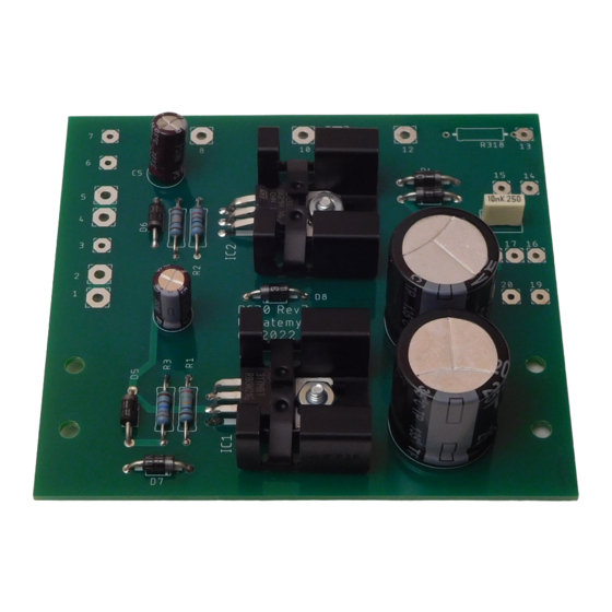
Page 9: Figure 2-Pc-30 Connections
Figure 4-PC-30 connections Page 9 of 11... -
Page 10: Figure 3-Pc30 Replacement Schematic
Figure 5-PC30 replacement schematic Page 10 of 11... -
Page 11: Installing The New Pc30
Installing the new PC30 Mount the PC30 to the bracket using the original hardware that you had previously set aside. Solder the labeled wires into the new numbered eyelets in the new PC30. Page 11 of 11...
Need help?
Do you have a question about the STEREO 400 and is the answer not in the manual?
Questions and answers