
Subscribe to Our Youtube Channel
Related Manuals for Krober O2

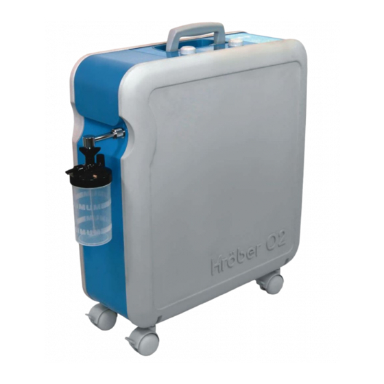
Summary of Contents for Krober O2
- Page 1 D.SPEC.02.B.00 Kröber O2 - Informations techniques_General_EN Technical Information Kröber O2 v. 28/06/2019...
- Page 2 D.SPEC.02.B.00 Kröber O2 - Informations techniques_General_EN Kröber O2 © Kröber Medizintechnik GmbH Salzheck 4 D-56332 Dieblich Tel.: +49 (0) 2607 9404 0 Fax: +49 (0) 2607 9404 22 E-Mail: info@kroeber.de Internet: www.kroeber.de Rev.: 1 v. 28/06/2019...
-
Page 3: Table Of Contents
1.1 General information......................5 1.2 Warranty......................... 5 2 Service ..........................7 2.1 Kröber O2........................7 2.1.1 Opening the Kröber O2 .................... 7 2.1.2 Closing the Kröber O2....................9 2.2 The functional unit ......................10 2.2.1 De-installing the functional unit ................11 2.2.2 Installing the functional unit.................. - Page 4 D.SPEC.02.B.00 Kröber O2 - Informations techniques_General_EN Kröber O2 5.4 Alarms........................... 42 5.4.1 Alarm priorities ....................... 42 5.4.2 Alarm categories ....................43 5.5 Symbols ........................47 v. 28/06/2019...
-
Page 5: Preliminary Remarks
Differing from our General Terms of Business we grant an extended warranty of 30.000 operating hours for all functional parts (e.g. compressor, control board, valve technology, etc.) used in our oxygen concentrator Kröber O2 . This extended warranty is valid for maximum 5 years from the date of purchase. - Page 6 D.SPEC.02.B.00 Kröber O2 - Informations techniques_General_EN Kröber O2 Preliminary remarks v. 28/06/2019...
-
Page 7: Service
D.SPEC.02.B.00 Kröber O2 - Informations techniques_General_EN Kröber O2 Service 2 Service 2.1 Kröber O2 2.1.1 Opening the Kröber O2 WARNING! Danger of electric current! Before opening, the unit must be switched off and disconnected from the mains supply. NOTE! For easy access to the unit, place the unit on a clean support. Empty and remove the installed humidifier first. - Page 8 D.SPEC.02.B.00 Kröber O2 - Informations techniques_General_EN Kröber O2 Service 4. In the opened unit there are the subassemblies: a. control PCB b. functional unit c. compressor d. fan and the components e. capacitor power cord v. 28/06/2019...
-
Page 9: Closing The Kröber O2
Kröber O2 Service 2.1.2 Closing the Kröber O2 NOTE! Closure of the Kröber O2 can be easily done with a device placed on the side. 1. Carefully re-install the grey housing cover and pay attention for a correct fit. 2. Insert all housing screws; screws... -
Page 10: The Functional Unit
D.SPEC.02.B.00 Kröber O2 - Informations techniques_General_EN Kröber O2 Service 2.2 The functional unit v. 28/06/2019... -
Page 11: Installing The Functional Unit
D.SPEC.02.B.00 Kröber O2 - Informations techniques_General_EN Kröber O2 Service 2.2.1 De-installing the functional unit 1. Remove the red connector of the solenoid wire from the control PCB. 2. Dismantle the EMC-core using an edge cutter. 3. Press the rim of quick connect at... - Page 12 D.SPEC.02.B.00 Kröber O2 - Informations techniques_General_EN Kröber O2 Service 4. Push the rim of the quick connect hose at the gas outlet of the functional unit smoothly and pull out the tubing. 5. Lift half-way the functional unit. 6. Push the rim of the quick connect...
-
Page 13: Installing The Functional Unit
D.SPEC.02.B.00 Kröber O2 - Informations techniques_General_EN Kröber O2 Service 2.2.2 Installing the functional unit 1. Remove the three protection caps from the inlets and outlets of the functional unit. 2. Guide the quick connect of the pressure sensor into the corresponding port of the functional unit. - Page 14 D.SPEC.02.B.00 Kröber O2 - Informations techniques_General_EN Kröber O2 Service 4. While inserting, pay attention to properly insert the exhaust muffler into the corresponding slot. 5. The exhaust muffler is in the correct end position if it is facing the compressor.
- Page 15 D.SPEC.02.B.00 Kröber O2 - Informations techniques_General_EN Kröber O2 Service 7. Attach the hose of the product gas outlet as far as it will go. 8. Install the quick connect hose as far as it will go into the air inlet of the functional unit.
- Page 16 D.SPEC.02.B.00 Kröber O2 - Informations techniques_General_EN Kröber O2 Service 10. Attach the red connector of the solenoid driver cable with the corresponding connector on the control PCB. Check polarity. The pin should be pointing towards the black box header. 11. Install the connector as far as it goes.
-
Page 17: The Fan
D.SPEC.02.B.00 Kröber O2 - Informations techniques_General_EN Kröber O2 Service 2.3 The fan 2.3.1 Disassembling the fan 1. Unfasten both wires of the fan at the terminal block on the control PCB. 2. Cut the cable tie of the cable harness with an edge cutter. - Page 18 D.SPEC.02.B.00 Kröber O2 - Informations techniques_General_EN Kröber O2 Service 3. Pull out the complete assembly (fan and air-cooler) half-way. If necessary unfasten the EMC- filter from the air-cooler. Note! Eventually re-adjust compressor wire and thereby release any tension! 4. Unfasten the 4 mounting screws of the fan.
-
Page 19: Installing The Fan
D.SPEC.02.B.00 Kröber O2 - Informations techniques_General_EN Kröber O2 Service 2.3.2 Installing the fan 1. When installing the fan, pay attention that the imprinted arrow (indicating the air flow) points towards the steel plate. 2. Screw the four mounting screws hand-tight. - Page 20 D.SPEC.02.B.00 Kröber O2 - Informations techniques_General_EN Kröber O2 Service 5. If necessary re-fasten the EMC- filter with a cable tie at the silicone hose of the air-cooler outlet. 6. Re-install the leads (no. 5 and 6) of the fan in the terminal block pos.
-
Page 21: Control Pcb
The control PCB contains sensitive electronic integrated circuits. Observe ESD (electrostatic discharge) precautions when disassembling and reassembling the Kröber O2 and when handling any of the components of the Kröber O2! 1. Disconnect all leads at the terminal block of the control PCB. - Page 22 D.SPEC.02.B.00 Kröber O2 - Informations techniques_General_EN Kröber O2 Service 2. Cut the cable tie of the power cord. 3. Bend all hoses and the cables aside. 4. Pull out the assembly of the control PCB and control panel by half way.
- Page 23 D.SPEC.02.B.00 Kröber O2 - Informations techniques_General_EN Kröber O2 Service 5. Pull the connecting hose off the pressure sensor. 6. Extract the control PCB completely, but do not put it down. 7. Disconnect the silicone hose from the multifunctional sensor. v. 28/06/2019...
- Page 24 D.SPEC.02.B.00 Kröber O2 - Informations techniques_General_EN Kröber O2 Service 8. Pull the temperature sensor out of the compressor compartment. 9. Remove the control PCB including plug-in panel entirely. 10. Remove both control elements by pulling them off. v. 28/06/2019...
- Page 25 D.SPEC.02.B.00 Kröber O2 - Informations techniques_General_EN Kröber O2 Service 11. Flip the control PCB and unscrew the 6 mounting screws. 12. Store the control PCB separately and ESD-protected. v. 28/06/2019...
-
Page 26: Installing The Control Pcb
The control PCB contains sensitive electronic integrated circuits. Observe ESD (electrostatic discharge) precautions when disassembling and reassembling the Kröber O2 and when handling any of the components of the Kröber O2. 1. Remove the transport packaging from the control PCB. - Page 27 D.SPEC.02.B.00 Kröber O2 - Informations techniques_General_EN Kröber O2 Service 3. Flip the assembly. Fit both control buttons on the corresponding components. 4. Uncoil entirely the temperature sensor wire and thread it through the corresponding hole into the compressor compartment. 5. Slide the control PCB including...
- Page 28 D.SPEC.02.B.00 Kröber O2 - Informations techniques_General_EN Kröber O2 Service 6. Re-install the silicone hose on the unconnected port of the multifunctional sensor. 7. Re-install the pressure sensing hose on the pressure sensor port. 8. Push the control PCB as far as it goes.
- Page 29 D.SPEC.02.B.00 Kröber O2 - Informations techniques_General_EN Kröber O2 Service 9. Fasten the power cord with a cable tie at the dome (right top in the figure). 10. Re-install all leads at the terminal blocks on the control PCB. To exclude mix-ups, the leads are numbered serially: no.
-
Page 30: The Compressor
D.SPEC.02.B.00 Kröber O2 - Informations techniques_General_EN Kröber O2 Service 2.5 The compressor 2.5.1 Removing the compressor 1. Disconnect leads no. 3 and 4 (compressor) at the terminal block of the control PCB. v. 28/06/2019... - Page 31 D.SPEC.02.B.00 Kröber O2 - Informations techniques_General_EN Kröber O2 Service 2. Cut the cable tie at the cable harness. 3. Pull the compressor cable through the grommet of the steel plate. 4. Disconnect connecting cable of the motor capacitor from the motor capacitor.
- Page 32 D.SPEC.02.B.00 Kröber O2 - Informations techniques_General_EN Kröber O2 Service 6. Pull compressor including support plate half-way out of the slots and hold it. 7. Open the clamp at the pressure outlet of the compressor using a screw driver and pull the hose from the nipple.
-
Page 33: Installing The Compressor
D.SPEC.02.B.00 Kröber O2 - Informations techniques_General_EN Kröber O2 Service 2.5.2 Installing the compressor 1. Slide compressor including support half-way down.. 2. Put a new clamp over the hose of the pressure outlet of the compressor. 3. Feed the pressure outlet hose over the stainless steel nipple. - Page 34 D.SPEC.02.B.00 Kröber O2 - Informations techniques_General_EN Kröber O2 Service 7. Feed the compressor wires through the grommet. 8. Also feed the motor capacitor wires through the grommet. NOTE! Because of the lugs, feed each wire separately through the grommet. 9. Connect the capacitor with the connection wires.
-
Page 35: Maintenance Procedures
D.SPEC.02.B.00 Kröber O2 - Informations techniques_General_EN Kröber O2 Maintenance procedures 3 Maintenance procedures 3.1 Safety inspection, annually If the KröberO2 is used in the home, the manufacturer specifies an annual safety inspection. determination and documentation of the oxygen concentration. determination and documentation of the oxygen flow. -
Page 36: Device Inlet Filter
4. Install the new filter element by careful rotations. 5. Close the service flap. 3.2.3 Device outlet filter The device outlet filter resides in the interior of the Kröber O2 before the gas exit and filters particles >8µ. 1. Open the KröberO2 (see chapter 2.1.1) 2. - Page 37 D.SPEC.02.B.00 Kröber O2 - Informations techniques_General_EN Kröber O2 Maintenance procedures 4. Install the new filter. Pay attention to the direction of the flow. The visible arrow on the filter should direct away from the solenoid towards the multifunctional sensor. 5. Close the Kröber O2.
-
Page 38: Recommendations For Re-Processoing
D.SPEC.02.B.00 Kröber O2 - Informations techniques_General_EN Kröber O2 Recommendations for re-processoing 4 Recommendations for re-processoing for accessories and consumables during the annual maintenance service 4.1 without change of the patient humidifier (reusable): clean and disinfect humidifier (non-reusable): dispose holder for humidifier: clean and disinfect tubing, nasal cannulas, masks etc.:... -
Page 39: Description Of Functions
Sieve bed A is supplied by inlet solenoid I1 and sieve bed B by inlet solenoid I2. Both outlet solenoids O1 and O2 vent the sieve beds A and B. The bound nitrogen is blown off through an exhaust muffler. The respectively inactive sieve bed is flushed with the product gas of the active sieve bed and is pre-charged at the end of each cycle with oxygen enriched air. -
Page 40: Control Pcb
D.SPEC.02.B.00 Kröber O2 - Informations techniques_General_EN Kröber O2 Description of functions 5.2 Control PCB Block diagram Funktional compressor interface unit 230 V temperature temperature solenoid terminal sensor alarm interface drivers block compressor Rotary On-/Off- device on/off encoder w user actions... -
Page 41: Flow Schematics
D.SPEC.02.B.00 Kröber O2 - Informations techniques_General_EN Kröber O2 Description of functions 5.3 Flow schematics v. 28/06/2019... - Page 42 D.SPEC.02.B.00 Kröber O2 - Informations techniques_General_EN Kröber O2 Description of functions 5.4 Alarms 5.4.1 Alarm priorities We differentiate between three alarm priorities: Alarm priority Description High priority: WARNING! Risk of health damage! Immediate countermeasures required to save the patient from any harm.
- Page 43 D.SPEC.02.B.00 Kröber O2 - Informations techniques_General_EN Kröber O2 Description of functions 5.4.2 Alarm categories Alarm category / Description LC display Temperature alarm High priority The operating temperature inside the concentrator is above 60°C. Countermeasures: – The unit should be switched off immediately.
- Page 44 Lack of oxygen High priority alarm The oxygen concentrator Kröber O2 is equipped with an innovative multi-function sensor to monitor the oxygen concentration of the oxygen output. If this drops below 60%, the lack of oxygen alarm is triggered.
- Page 45 LC display Oxygen status Low priority alarm The oxygen concentrator Kröber O2 is equipped with an innovative multi-function sensor to monitor the oxygen concentration of the oxygen output. If this drops below 82%, the oxygen status alarm is triggered. Countermeasures –...
- Page 46 D.SPEC.02.B.00 Kröber O2 - Informations techniques_General_EN Kröber O2 Description of functions Alarm category / Description LC display Volume flow alarm Medium priority The actual volume flow does not match the setting. Countermeasures – Check whether the oxygen hose is buckled or squeezed.
- Page 47 D.SPEC.02.B.00 Kröber O2 - Informations techniques_General_EN Kröber O2 Description of functions 5.5 Symbols Symbol Explanation Warning, consult instructions for use. Applied part type BF Degree of protection II Notified Body TÜV Rheinland I / O Power On/Off v. 28/06/2019...
Need help?
Do you have a question about the O2 and is the answer not in the manual?
Questions and answers