Table of Contents
Advertisement
Advertisement
Table of Contents

Summary of Contents for Ink Bird IVC-001W
- Page 1 尺寸:130x160mm 类型:骑马钉...
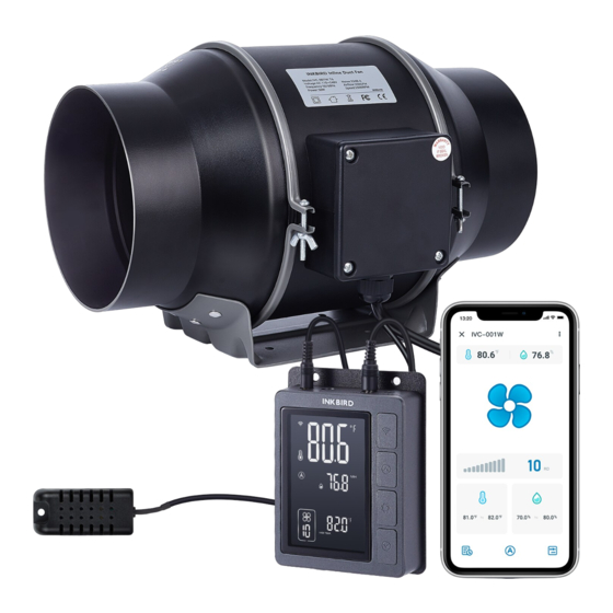
- Page 2 Smart Fan Controller Inline Duct Fan IVC-001W...
-
Page 4: Table Of Contents
CONTENTS Overview Features & Specifications Product Contents INKBIRD App Smart Controller Instructions Automatic Control Mode Instructions Manual Control Mode Instructions Timer Control Mode Instructions Shutdown Mode Lock Mode ECO Mode Parameter Factory Setting Inline Duct Fan Installation Instructions FCC Requirement... -
Page 5: Overview
01 Overview 02 Features & Specifications Shutdown RH(%RH) maximal tolerance typical tolerance 90 100 Relative Humidity(%RH) -
Page 6: Product Contents
T(℃) +1.5 maximal tolerance typical tolerance +1.0 +0.5 +0.0 -40 -20 100 120 Temperature(℃) 03 Product Contents Smart Controller Unit MACHINE SCREWS WOOD SCREWS WOOD SCREWS SMART SENSOR (WALL MOUNT) (WALL MOUNT) (WALL HANG) CONTROLLER PROBE (X2) (X2) (X2) (X1) (X1) Inline Duct Fan Unit INLINE DUCT... -
Page 7: Inkbird App
04 INKBIRD App 05 Smart Controller Instructions WORK1 WORK2... -
Page 8: Automatic Control Mode Instructions
06 Automatic Control Mode Instructions The fan will run at the set fan speed according to the relationship between the current temperature and humidity and the trigger target temperature and humidity. How to set the fan to run at a fan speed of 10 to keep the temperature at 81.0℉ to 82.0℉... - Page 9 Step2: Press and hold the button for Step1: Press the button to select 2 seconds to enter the setting mode, or automatic control mode, in which the press button to enter the quick symbol is displayed. setting mode, in which “SETTING” is displayed.
- Page 10 Step5: Press the button to select the Step6: Press the button to select the high-humidity trigger value. “HIGH low-humidity trigger value. “LOW HUMD.” HUMD.” is displayed and the is displayed and the corresponding corresponding parameter flashes. Press parameter flashes. Press the button to adjust the button to adjust the low-humidity trigger high-humidity trigger value to 80.0%RH.
- Page 11 Fan status Humidity trigger value 70.0%RH 80.0%RH How to disable the high-temperature trigger function? Step2: Press and hold the button for 2 Step1: Press the button to select seconds to enter the setting mode. Press automatic control mode, in which the button to select the high-temperature symbol is displayed.
- Page 12 Step3: Press and hold the button for 2 seconds or no operation for 60 seconds to quit the setting state and save the set parameters. Low-temperature trigger, high-humidity trigger, and low-humidity trigger functions can be turned off by referring to the above steps. Note that at least one trigger function should remain on.
-
Page 13: Manual Control Mode Instructions
Step3: Press and hold the button for 2 seconds or no operation for 60 seconds to quit the setting state and save the set parameters. Note: When setting the high-temperature alarm value/low-temperature alarm value/high-humidity alarm value/low-humidity alarm value, press and hold the buttons simultaneously for 2 seconds to display SETTING OFF and disable the corresponding alarm function. -
Page 14: Timer Control Mode Instructions
Step3: Press the button to select the Step4: Step4: Press and hold button for fan run time. Press the button 2 seconds or no operation for 60 seconds to adjust the time display (or 5 seconds in the quick setting mode) to quit the setting state and save the set parameters. - Page 15 Step1: Press the button to select Step2: Press and hold the button for 2 the timer mode, in which the seconds, or press the button to enter symbol is displayed. the setting mode. SUN. MON. TUES. WED. THURS. FRI. SAT. SUN.
- Page 16 Step5: Press the button to set the run Step6: Press the button to set the fan time of segment 1, and “TIME SETTING” is speed of segment 1, and the fan symbol displayed. Press the button to is displayed. Press the button to adjust the run time to 02:00.
-
Page 17: Shutdown Mode
09 Shutdown Mode All control functions are disabled. Press the button to select the shutdown mode, in which all functional controls are turned off. 10 Lock Mode In the non-setting state, press and hold the button for 2 seconds simultaneously to turn on/off the lock function. - Page 18 13 Duct Fan Instructions Bottom Duct-B Duct-A Impelle Frame Hoops cover Screw Power cover Duct Butt plate DC Connect Wire (2.4m length 26AWG) AC Power Cord (1.8m length 18AWG)
- Page 19 Installation Instructions Step1: Unscrew the annular threaded nail Step2: Remove the power supply chassis of the duct fan. from the rack. Step3: Use the mounting holes of the Step4: Drill four holes at the marked flange bracket to mark the position to be locations.
- Page 20 Step5: If you need plastic expansion tubes, Step6: Align the hole of the flange bracket insert the included 4 expansion tubes into with the wall anchor, and use a screwdriver the drilled holes and fix them in the holes or drill to insert the four screws to fix the with a hammer.
- Page 21 Step9: Put the metal ring back onto the Step10: When installing the duct, use the flange and tighten the screws to fix the included duct clamps to secure it to fan. either end of the duct fan, making sure it is tightly sealed.
- Page 22 Intake & Exhaust This duct fan can be used as an intake machine or exhaust machine in greenhouses and large grow tents. For optimal ventilation of the space, intake fans or openings (without fans) must be placed in the bottom corners of the growing space, and exhaust fans must be hung (as shown below) or mounted in the corresponding highest corners.
- Page 23 Controller Power Up and Setting Step 1: Mark the locations to be mounted Step2: Drill 2 holes at the marked locations. with the mounting holes on the controller. Pay attention to the fan power cable length and the probe length. Step3: If you need plastic expansion Step4: Align the mounting holes on the tubes, insert the included 2 expansion...
- Page 24 Step5: You can organize your cables Step6: Insert the probe of the duct fan into using the included tie bracket, screws, the WORK1/WORK2 port of the controller. and cable ties. Use screws to secure the cable tie to the surface. Wrap the cable tie around the rope and put it into the tie bracket.
- Page 25 Add More Fans This smart controller can control two fans simultaneously. Insert the two fans into the WORK1 and WORK 2 ports separately, as shown below: Dual Connection IVC-001W T6 IVC-001W T6 Cleaning & Maintenance Step1: Remove the power supply chassis Step2: Use a wet cloth to remove dust and from the flange.
-
Page 26: Fcc Requirement
Step3: Remove dust and debris from the Step4: See steps 7 to 9 in the installation other side of the stator blade and clean instructions to secure the power supply the inner areas of the intake and exhaust chassis on the flange. flanges. - Page 27 – Reorient or relocate the receiving antenna. – Increase the separation between the equipment and receiver. – Connect the equipment into an outlet on a circuit different from that to which the receiver is connected. – Consult the dealer or an experienced radio/TV technician for help. This equipment complies with FCC radiation exposure limits set forth for an uncontrolled environment.
- Page 28 Attached Table 2: Parameter Description In Automatic Mode Icon Function Setting Range Default Setting CF:F Temperature Unit ℃ or ℉ ℉ Fan Speed 0~10 -40℃~100℃/-40℉~212℉ High-temperature 25.0℃/77.0℉ or OFF (disable High Temp. trigger value high-temperature trigger) 40℃~100℃/-40℉~212℉ Low-temperature 20.0℃/68.0℉ or OFF (disable Low Temp.
- Page 30 V1.0...
Need help?
Do you have a question about the IVC-001W and is the answer not in the manual?
Questions and answers