Advertisement
Quick Links
Advertisement

Summary of Contents for FLAJZAR GSM-DIN4
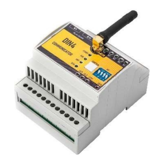
- Page 1 GSM-DIN4 GSM communicator on DIN rail INSTRUCTION Last updating 26.5.2020 1|EN...
- Page 2 SMS or by mere calling through (free of charge), or by using the function of a timer or a thermostat with connected external temperature sensor. The communicator GSM-DIN4 is equipped with five logic inputs which can be connected with any sensor. Moreover, it has two measuring (analogue) inputs.
- Page 3 Input for 4 temperature sensors with measuring range from - 20°C to 125°C. (Only the type recommended by the producer can be connected. It is possible to buy it under the product code TC530C2 or TC530C5) Simple configuration through WiFi interface by means of integrated web environment ...
- Page 4 HEATING ON, SWITCH THE HEATING OFF ...) Status of the device can be checked any time by SMS message. GSM-DIN4 can be easily and quickly configured through the well-arranged and intuitive web environment which is accessible through the internal WiFi net.
- Page 5 Description of the teminal block 5|EN...
- Page 6 Description of the terminals 01-+ contact of temperature sensors (supply No. TC530Cx) 02- - contact of temperature sensors (supply No. TC530Cx) 03- 12V DC for the analogue (measuring) inputs. 04- Analogue input A1 05- Analogue input A2 06- GND for the analogue (measuring) inputs 07- 12V DC for the logic inputs 08- Logic input IN1 09- Logic input IN2...
- Page 7 Description of connectors and slots SD- Slot for microSD cards for saving the history (PUSH- PUSH) SIM- Slot for microSIM cards (PUSH-PUSH) SMA- Connector for connecting GSM antenna Description of DIP switch DIP1 DIP2 DIP3 DIP4 Position DIN4 Automate WiFi regime Position DIN4...
- Page 8 Description of LED signalling Green is off - the input in not connected IN1- IN5 (green) Green is on - the input is connected POWER Green is off - DIN4 is off (green) Green is on - DIN4 is on Yellow is off - the automat is in the STOP (yellow) regime, evaluating loop is stopped;...
- Page 9 Connect terminals 13 and 14 to the power supply of 230V or 24V according to the device version. After switching the communicator GSM-DIN4 on, switch over DIP1 to the position ON and the green LED diode POWER will be on.
- Page 10 Installation of GSM-DIN4 communicator As the device is supplied from the network voltage of 230V, its installation should be carried out by a specialist with appropriate qualification. Caution: incorrect connection of sensors can cause unreliable operation of the device or even its damage.
- Page 11 Configuration of GSM-DIN4 communicator The configuration is carried out through WiFi interface which can be operated in AP or Client regime. AP regime (access point) - DIP4 ON - communicator transmits its own WiFi net with the name DIN4. Connection to the net is possible through the medium of notebook, tablet, or smart mobile phone with WiFi.
- Page 12 Desccription of the configuration pages The pages can be switched into CZ or EN in the upper MENU by clicking on the appropriate flag. Noticeboard - the page displays the current status of communicator, e.g. date, time, strength of GSM signal, parameters of WiFi interface, properties and current status of logic inputs, status of analogue inputs, measured values of temperature sensors if they are...
- Page 13 Analogue inputs – the page contains the configuration of analogue inputs A1 and A2. It is possible to set the name of an individual input, SMS order for the inquiry about the current values of input, the alarm function while reaching the upper or lower limit of the input and the recount of measured value.
- Page 14 the communicator is connected to the net with the access to the Internet, saving or downloading the configuration file for the communicator configuration, saving and downloading the file for users‘ configuration, the possibility of saving and deleting the files from the history of GSM communication, the analogue inputs or the log of temperature sensors and the possibility of configuration of the device into the factory configuration.
- Page 15 The font size in SMS orders is irrelevant - you can write the order for the status determination as STATUS/status/StAtus Configuration SMS orders are in GSM-DIN4 intended only as a stopgap just in case the configuration is not possible through WiFi.
- Page 16 Description SMS order STATUS Determination of the current status of communicator (operator, status of signal, status of credit, number of SMS sent off, regime of WiFi, IP address, regime of automat and status of SD card). INPUTS Determination of the current status of logic and analogue inputs.
- Page 17 New versions of firmware, new functions GSM-DIN4 is designed as an open system which will be further developed according to the clients’ requirements. So the system updating is possible. The firmware updating is carried out through the configuration pages.
- Page 18 Conformity declaration for the device. This document and other documents can be downloaded www.flajzar.cz As the product is a wireless device, specific unfavourable external events can cause the loss of connection with the device (which generally refers to all radio devices).
- Page 19 The producer is not responsible for the device malfunction which was caused by the operator after expiration of the date stated in the introduction of this Instruction as well as for the damages caused by inappropriate usage and connection. GSM DIN4 was tested with SIM cards of all Czech, Slovak and other selected foreign operators.
- Page 20 698 01 Veselí nad Moravou E-mail:obchod@flajzar.cz www.flajzar.cz Tel.:+420 776 586 866 Send your technical inquiry concerning the device by email to technik@flajzar.cz. Copying of the Instruction or its parts is possible only upon the written consent of the firm FLAJZAR,s.r.o 20|EN...