Advertisement
Available languages
Available languages
Quick Links
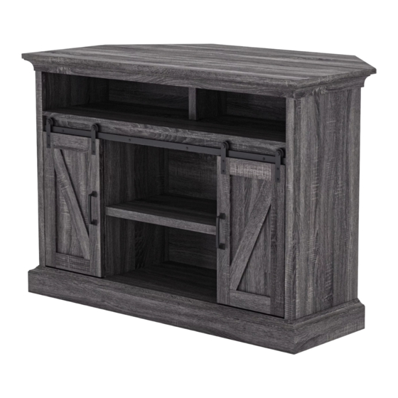
Allston Barn Door Corner TV Stand
If you have any questions regarding assembly or if parts are missing, DO NOT return this item to the
store where it was purchased. Please call our customer service number and have your instructions
and parts list ready to provide the model name, part name or factory number:
Pacific Standard Time: 8:30 a.m. - 4:30 p.m., Monday - Friday
Or visit our web site 24 hours a day, 7 days a week for product assistance at
THIS INSTRUCTION BOOKLET CONTAINS IMPORTANT SAFETY INFORMATION.
for TV's up to 55 inch
MODEL # WHA-10009
ADULT ASSEMBLY REQUIRED
www.whalenstyle.com
Or e-mail your request to parts@whalenfurniture.com
PLEASE READ AND KEEP FOR FUTURE REFERENCE.
Date 2020-06-02
# WHA-10009-DG
866-942-5362
Rev. 0001-A
LOT NUMBER:
DATE PURCHASED:
/
/
Advertisement

Summary of Contents for WHALL WHA-10009
- Page 1 DATE PURCHASED: Allston Barn Door Corner TV Stand for TV’s up to 55 inch MODEL # WHA-10009 # WHA-10009-DG ADULT ASSEMBLY REQUIRED If you have any questions regarding assembly or if parts are missing, DO NOT return this item to the store where it was purchased.
-
Page 2: Special Note
M A X I M U M R E C O M M E N D E D W E I G H T L O A D S MANUFACTURER: Whalen Furniture Manufacturing CATALOG: Allston Barn Door Corner TV Stand for TV’s up to 55 inch MODEL # WHA-10009 / WHA-10009-DG FITS UP TO MOST 139.7 cm / 55” DIAGONAL FLAT PANEL TVs MAXIMUM LOAD 61.2 kg / 135 lb... - Page 3 IMPORTANT Before you begin: Open, identify and count all parts prior to assembly. Lay out parts on a flat and non-abrasive surface. You will need the parts identified on page 4 and 5 of this instruction manuals. NOTE: IT IS VERY IMPORTANT TO USE GLUE WITH THE DOWELS. EXCESS GLUE CAN BE WIPED OFF WITH A DAMP CLOTH.
- Page 4 Parts and Hardware List Please read completely through the instructions and verify that all listed parts and hardware are present before beginning assembly. A- Top Panel (Qty. 1) B- Top Corner Extension (Qty. 1) C- Fixed Shelf (Qty. 1) D- Bottom Panel (Qty. 1) E- Left Side Panel (Qty.
- Page 5 Parts and Hardware List Please read completely through the instructions and verify that all listed parts and hardware are present before beginning assembly. (1) Cam Lock (2) Cam Bolt (3) M8 x 30 mm Wood Dowel (Qty. 44+2 extra) (Qty. 44+2 extra) (Qty.
- Page 6 Assembly Instructions ② x 24 1. Unpack the unit and confirm that you have all the hardware and required parts. Assemble the unit on a carpeted floor or the empty carton to avoid any scratch. 2. Securely screw the Cam Bolts (2) into the designated small holes on the Top Panel (A), Side Panels (E and F) and Side Panel Moldings (L) using a Phillips screwdriver.
- Page 7 Assembly Instructions ② x 18 3. Securely screw the Cam Bolts (2) into the designated small holes on the Fixed Shelf (C), Upper Partition Panel Molding (H) and Bottom Panel (D) using a Phillips screwdriver.
- Page 8 Assembly Instructions ③ x 8 4. Glue the 30 mm Wood Dowels (3) into the inner holes of Side Panels (E and F). NOTE: It is very important to use a small amount of glue on both ends of dowels.
- Page 9 Assembly Instructions ① x 6 5. Align and attach one Side Panel Molding (L) to the Left Side Panel (E) by engaging 3 Cam Locks (1) (Refer to page 3 on Cam Lock system operation supplement). 6. Repeat the same procedure to combine the other Side Panel Molding (L) to the Right Side Panel (F).
- Page 10 Assembly Instructions ③ x 17 7. Glue the 30 mm Wood Dowels (3) into the inner holes of Fixed Shelf (C), Lower Partition Panels (I and J) and Middle Crossbar (K).
- Page 11 Assembly Instructions ① x 4 8. Align and attach the Middle Crossbar (K) to the Fixed Shelf (C) by engaging 4 Cam Locks (1).
- Page 12 Assembly Instructions ① x 4 9. Align and attach the Lower Partition Panels (I and J) to the Fixed Shelf (C) by engaging 4 Cam Locks (1).
- Page 13 Assembly Instructions ③ x 14 10. Glue the 30 mm Wood Dowels (3) into the inner holes of Bottom Panel (D), Bottom Stretchers (N and O) and Bottom Front Molding (M).
- Page 14 Assembly Instructions ① x 4 11. Align and attach the Bottom Back Stretcher (O) to the Bottom Panel (D) by engaging 4 Cam Locks (1).
- Page 15 Assembly Instructions ④ x 4 12. Attach the Bottom Panel assembly to the Lower Partition Panels (I and J) with four 50 mm Screws (4).
- Page 16 Assembly Instructions ① x 12 13. Align the large holes on Left Side Panel (E) with the inserted Wood Dowels (3) on the assembled unit. Firmly press them together and fasten it in place by engaging 6 Cam Locks (1). 14.
- Page 17 Assembly Instructions 15. Attach the Bottom Front Stretcher (N) to the Bottom Panel (D).
- Page 18 Assembly Instructions ① x 4 16. Fasten the Bottom Front Stretcher (N) to the Bottom Panel (D) by engaging 4 Cam Locks (1).
- Page 19 Assembly Instructions ④ x 4 17. Secure the Bottom Front Stretcher (N) to the Side Panels (E and F) with four 50 mm Wood Screws (4).
- Page 20 Assembly Instructions ⑤ x 8 18. Attach the Bottom Front Molding (M) to the Bottom Front Stretcher (N) with eight 25 mm Screws (5).
- Page 21 Assembly Instructions ⑥ x 2 19. Install the Floor Levelers (6) to the bottom of the Bottom Front Molding (M). Adjust the levelers in the correct height.
- Page 22 Assembly Instructions ② x 2 20. Stand the unit upright. 21. Securely screw the Cam Bolts (2) into the designated small holes on the Fixed Shelf (C) using a Phillips screwdriver.
- Page 23 Assembly Instructions ① x 2 ③ x 2 22. Glue the 30 mm Wood Dowels (3) into the inner holes of Upper Partition Panel (G). 23. Fasten the Upper Partition Panel Molding (H) to the Upper Partition Panel (G) by engaging 2 Cam Locks (1).
- Page 24 Assembly Instructions ② x 2 24. Attach the Upper Partition Panel assembly to the Fixed Shelf (C) by engaging 2 Cam Locks (1).
- Page 25 Assembly Instructions ① x 6 25. Ask for assistance to position the Top Panel (A) onto the inserted Wood Dowels (3). Attach the Top Panel (A) in place by engaging 6 Cam Locks (1).
- Page 26 Assembly Instructions ⑧ x 34 26. Now, go back and securely tighten all the cam locks and screws. Make sure that all the parts are tight and there are no gaps between the parts. This will help keep the unit square. 27.
- Page 27 Assembly Instructions ⑦ x 4 30. Stand the unit upright. 31. Using the pilot holes as a guide, fasten two L-Shaped Metal Brackets (11) to the Bottom Panel (D) with four 15 mm Flat Head Screws (7).
- Page 28 Assembly Instructions ⑩ x 4 ⑨ x 2 32. Attach 2 Handles (9) to the front side of Doors (R and S) with the provided Handle Bolts (10).
- Page 29 Assembly Instructions 33. Hook 4 Door Rollers (12) onto the pre-attached hanging bar on the Middle Crossbar (K).
- Page 30 Assembly Instructions 34. Take the Left Door (R) and fit the bottom groove onto the installed L-Shaped Metal Brackets (11) on Bottom Panel (D) properly. Proceed to attach the two Door Rollers (12) to the top portion of the Left Door (R) with four 19 mm Screws (13), using the pilot holes as a guide.
- Page 31 Assembly Instructions 36. Insert four Shelf Supports (15) into the holes at your desired height inside each side compartment. Tilt and rest the Small Adjustable Shelves (Q) onto the Shelf Supports (15). Secure the shelf in place with the 12 mm Wood Screws (14) for extra support.
- Page 32 Assembly Instructions 37. Plug the Cam Lock Covers (16) onto the visible Cams Locks to conceal the Cams. 38. Stick the Rubber Bumpers (20) at the outer edges of the Doors (R and S) to avoid slamming the doors.
- Page 33 Assembly Instructions 39. Insert four Shelf Supports (15) into the holes at your desired height inside middle compartment. Tilt and rest the Large Adjustable Shelves (P) onto the Shelf Supports (15). Secure the shelf in place with the 12 mm Wood Screws (14) for extra support.
- Page 34 Assembly Instructions ⑤ x 3 40. Glue two 20 mm Wood Dowels (19) as a guide, combine the Corner Short Support (U) and Long Support (T) together with three 25 mm Screws (5). 41. Flip last assembly around and fasten two Plastic Connectors (17) to the end of Corner Long and Short Supports (T and U) with one 1/2”...
- Page 35 Assembly Instructions ③ x 4 42. Glue four 30 mm Wood Dowels (3) into the drilled holes on the front edge of the the Top Corner Extension (B) as a guide. Align and fasten three Plastic Connectors (17) to the Top Corner Extension (B) with the 1/2” Bolts (18).
- Page 36 Assembly Instructions 43. Align and attach the Corner Long Support (T) to the Top Corner Extension (B) with one 1/2” Bolt (18).
- Page 37 Assembly Instructions 44. Align and attach the assembled Corner Extension to the Top Panel (A) and the Bottom Back Stretcher (O) with four 1/2” Bolts (18).
- Page 38 Assembly Instructions NOTE: To prevent your TV from tipping, you must follow these instructions if you place a TV on top of your console. Otherwise, skip to “Step 46”. 45. Remove the paper backing from the Stop Rail (X), then properly align the Stop Rail with the top edge of the stopper template on Top Panel (A).
- Page 39 Assembly Instructions Tools required: Phillips screwdriver, stud finder, pencil, tape measure, power drill and 1/8” drill Bit. 47. Ask for assistance to position the assemble stand at the desired location against a wall. If necessary, adjust the installed Floor Levelers at the bottom of the unit to level the unit. Now, follow the instructions printed on the plastic bag containing the Tipping Restraint Hardware to attach the tip-over restraints to the unit and the wall.
-
Page 40: Care And Maintenance
Care and Maintenance Use a soft, clean cloth that will not scratch the surface when dusting. Use of furniture polish is not necessary. Should you choose to use polish, test first in an inconspicuous area. Using solvents of any kind on your furniture may damage your furniture’s finish. ... - Page 41 FECHA de COMPRA: / Consola de TV esquina Allston con puerta de granero para TV’s de hasta 55 pulgadas Modelo # WHA-10009 # WHA-10009-DG ENSAMBLE REQUERIDO POR ADULTOS Si tiene alguna pregunta relacionada con el montaje o si faltan piezas, NO devuelva este producto al establecimiento donde lo adquirió.
- Page 42 M Á X I M O P E S O R E C O M E N D A D O FABRICANTE: Whalen Furniture Manufacturing CATALOGO: Consola de TV esquina Allston con puerta de granero para TV’s de hasta 55 pulgadas MODELO # WHA-10009 / WHA-10009-DG PARA LA MAYORIA TV’S DE HASTA 139.7 cm / 55”...
- Page 43 IMPORTANTE Antes de comenzar: Abra, identifique y cuente todas las partes antes del ensamble. Coloque las piezas sobre una superficie plana y no abrasiva. Tendrá que las partes identificadas en la página 4 y 5 de este manual de instrucciones. NOTA: ES MUY IMPORTANTE PARA EL USO DE GOMA CON LOS PERNSO DE MADERA.
- Page 44 Lista de partes y material de ferretería Le rogamos que lea completamente las instrucciones y verifique que todas las piezas y herramientas indicadas se encuentran presentes antes del comienzo del montaje. A- Panel superior (Cant. 1) B- Extensión superior de la esquina (Cant. 1) C- Repisa fija (Cant.
- Page 45 Lista de partes y material de ferretería Le rogamos que lea completamente las instrucciones y verifique que todas las piezas y herramientas indicadas se encuentran presentes antes del comienzo del montaje. (1) Tuerca de fijación (2) Perno de fijación (3) Clavija de madera de M8 x 30 mm (Cant.
- Page 46 Instructivo de ensamble ② x 24 1. Desempacar la unidad y confirmar que se tiene todo el material de ferretería y partes requeridas. Ensamblar la unidad en un piso alfombrado o en el cartón vacío para evitar rasguños. 2. Atornillar los pernos de fijación (2) en los agujeros chicos designados en el panel superior (A), en los paneles laterales (E y F) y las molduras del panel lateral (L) usando el desarmador estrella.
- Page 47 Instructivo de ensamble ② x 18 3. Atornillar los pernos de fijación (2) en los agujeros chicos designados en la repisa fija (C), en la moldura del panel divisor superior (H) y en el panel inferior (D) usando el desarmador estrella.
- Page 48 Instructivo de ensamble ③ x 8 4. Pegar la clavija de madera de 30 mm (3) en los agujeros interiores de los paneles laterales (E y F). NOTA: Usar una cantidad pequeña de pegamento en ambos lados de las clavijas.
- Page 49 Instructivo de ensamble ① x 6 5. Alinear y adjuntar una moldura del panel lateral (L) al panel izquierdo (E) empleando 3 tuercas de fijación (1) (Consulte la página 3 del sistema de tuerca de fijación). 6. Repetir el mismo procedimiento para combinar la otra moldura del panel lateral (L) al panel derecho (F).
- Page 50 Instructivo de ensamble ③ x 17 7. Pegar las clavijas de madera de 30 mm (3) en los agujeros interiores de la repisa fija (C), de los paneles divisores inferiores (I y J) y el soporte medio (K).
- Page 51 Instructivo de ensamble ① x 4 8. Alinear y adjuntar el soporte medio (K) a la repisa fija (C) empleando 4 tuercas de fijación (1).
- Page 52 Instructivo de ensamble ① x 4 9. Alinear y adjuntar los paneles divisores inferiores (I y J) a la repisa fija (C) empleando 4 tuercas de fijación (1).
- Page 53 Instructivo de ensamble ③ x 14 10. Pegar clavijas de madera de 30 mm (3) en los agujeros interiores del panel inferior (D), de los soportes inferiores (N y O) y la moldura inferior frontal (M).
- Page 54 Instructivo de ensamble ① x 4 11. Alinear y adjuntar el soporte inferior posterior (O) al panel inferior (D) empleando 4 tuercas de fijación (1).
- Page 55 Instructivo de ensamble ④ x 4 12. Adjuntar el ensamble del panel inferior a los paneles divisores inferiores (I y J) con 4 pernos de 50 mm (4).
- Page 56 Instructivo de ensamble ① x 12 13. Alinear los agujeros grandes en el panel izquierdo (E) con las clavijas de madera insertadas (3) en la unidad ensamblada. Presionar para juntar y sujetar en su lugar empleando 6 tuercas de fijación (1). 14.
- Page 57 Instructivo de ensamble 15. Adjuntar el soporte inferior frontal (N) al panel inferior (D).
- Page 58 Instructivo de ensamble ① x 4 16. Sujetar el soporte inferior frontal (N) al panel inferior (D) empleando 4 tuercas de fijación (1).
- Page 59 Instructivo de ensamble ④ x 4 17. Asegurar el soporte inferior frontal (N) a los paneles laterales (E y F) con 4 clavijas de madera de 50 mm (4).
- Page 60 Instructivo de ensamble ⑤ x 8 18. Adjuntar la moldura inferior frontal (M) al soporte inferior frontal (N) con 8 pernos de 25 mm (5).
- Page 61 Instructivo de ensamble ⑥ x 2 19. Instalar los niveladores de piso (6) a la parte inferior de la moldura inferior frontal (M). Ajustar los niveladores a la altura correcta.
- Page 62 Instructivo de ensamble ② x 2 20. Poner la unidad en posición vertical. 21. Atornillar los pernos de fijación (2) en los agujeros chicos designados en la repisa fija (C) usando el desarmador estrella.
- Page 63 Instructivo de ensamble ① x 2 ③ x 2 22. Pegar las clavijas de madera de 30 mm (3) en los agujeros internos del panel divisor superior (G). 23. Sujetar la moldura del panel divisor superior (H) al panel divisor superior (G) empleando 2 tuercas de fijación (1).
- Page 64 Instructivo de ensamble ② x 2 24. Adjuntar el ensamble del panel divisor superior a la repisa fija (C) empleando 2 tuercas de fijación (1).
- Page 65 Instructivo de ensamble ① x 6 25. Pedir asistencia para posicionar el panel superior (A) sobre las clavijas de madera insertadas (3). Adjuntar el panel superior (A) en su lugar empleando 6 tuercas de fijación (1).
- Page 66 Instructivo de ensamble ⑧ x 34 26. Ahora, volver y apretar todas las tuercas de fijación y los pernos, asegurar que todas las partes estén apretadas y de que no hay huecos entre las partes, esto ayudara a mantener la unidad cuadrada. 27.
- Page 67 Instructivo de ensamble ⑦ x 4 30. Poner la unidad en posición vertical. 31. Usando loa agujeros pilotos como guía, sujetar 2 soportes de metal L (11) al panel inferior (D) con 4 pernos de cabeza plana de 15 mm (7).
- Page 68 Instructivo de ensamble ⑩ x 4 ⑨ x 2 32. Adjuntar 2 manijas (9) al lado frontal de las puertas (R y S) con los pernos de manija provistos (10).
- Page 69 Instructivo de ensamble 33. Enganchar 4 rodillos de puerta (12) sobre las barras enganchadas pre-adjuntadas en el soporte medio (K).
- Page 70 Instructivo de ensamble 34. Tomar la puerta izquierda (R) y meter la ranura inferior en los soportes de metal L instalados (11) en el panel inferior (D). Proceder para adjuntar 2 rodillos de puerta (12) a la porción superior de la puerta izquierda (R) con 4 pernos de 19 mm (13), usando los agujeros pilotos como guía.
- Page 71 Instructivo de ensamble 36. Insertar 4 soportes de repisa (15) en los agujeros a su altura deseada adentro de cada compartimiento lateral. Voltear y descansar las repisas ajustables pequeñas (Q) sobre los soportes de repisa (15). Asegurar la repisa en su lugar con los pernos para madera de 12 mm (14) para soporte extra.
- Page 72 Instructivo de ensamble 37. Colocar las tapas de las tuercas de fijación (16) sobre las tuercas de fijación visibles para esconder. 38. Pegar los topes de plástico (20) en los bordes exteriores de las puertas (R y S) para evitar cerrar de golpe las puertas.
- Page 73 Instructivo de ensamble 39. Insertar 4 soportes de repisa (15) en los agujeros a su altura deseada adentro del compartimiento medio. Voltear y descansar las repisas ajustables grandes (P) sobre los soportes de repisa (15). Asegurar la repisa en su lugar con los pernos para madera de 12 mm (14) para soporte extra.
- Page 74 Instructivo de ensamble ⑤ x 3 40. Pegar 2 clavijas de madera de 20 mm (19) como guía, combinar el soporte de esquina corto (U) y el soporte largo (T) con 3 pernos de 25 mm (5). 41. Voltear el esnamble previo y sujetar 2 conectores de plástico (17) al extremo de los soporte de esquina largo y corto (T y U) con un perno de 1/2”...
- Page 75 Instructivo de ensamble ③ x 4 42. Pegar 4 clavijas de madera de 30 mm (3) en los agujeros perforados en el borde frontal de la extensión superio de la esquina (B) como guía. Alinear y sujetar 3 conectores de plástico (17) a la extensión superior de la esquina (B) con los pernos de 1/2”...
- Page 76 Instructivo de ensamble 43. Alinear y adjuntar el soporte de la esquina largo (T) a la extensión superior de la esquina (B) con un oerno de 1/2” (18).
- Page 77 Instructivo de ensamble 44. Alinear y adjuntar la extensión de la esquina ensamblada al panel superior (A) y al soporte inferior posterior (O) con 4 pernos de 1/2” (18).
- Page 78 Instructivo de ensamble NOTA: Para evitar que su televisor su vuelque, se debe seguir estas instrucciones cuando se ubique su televisor en el mueble. Delo contrario, vaya al paso 46. 45. Retirar el respaldo de papel del riel tope (X), luego alinear el riel tope con el borde superior del templete del tope en el panel superior (A).
- Page 79 Instructivo de ensamble Herramientas Requeridas: Desarmador estrella, localizador de barrotes, lápiz, cinta de medir, taladro eléctrico y broca de 0.1 pulgada. 47. Pida assistencia para posicionar la chimenea ensamblada en el lugar deseado contra la pared. Si fuera necessario, ajuste los niveladores de piso adjuntados en la parte inferior de la base para nivelar la unidad.
-
Page 80: Mantenimiento Y Cuidados
Mantenimiento y Cuidados Use una toalla suave y limpia para evitar daños y rayaduras. Uso de cera para pulir muebles no es necesario. Si desea usar cera, pruebela en un área que no sea visible para revisar su funcionamiento. ...
Need help?
Do you have a question about the WHA-10009 and is the answer not in the manual?
Questions and answers