Table of Contents
Advertisement
Quick Links
Advertisement
Table of Contents

Summary of Contents for Mars Labs Titan CAI
- Page 2 Although this manual is believed to be correct at the time of publication, Mars Labs, its employees, or agents involved in the preparation and publication of this manual do not accept any form of liability for its contents or any consequences arising from its use.
-
Page 3: Table Of Contents
Titan CAI Table of Contents Introduction Furnished Accessories ..................Support ......................General Guidelines and Warnings ..............Guidelines for Wiring Sensors ................. Operation Front Panel ....................... Rear Panel ......................Signal Flow ..................... Calibration Modes .................... Formatting Memory Cards ................Interface Analog Input Connector ................... -
Page 4: Furnished Accessories
Titan CAI - Introduction Introduction The Titan CAI Mini-Recorder is a fully integrated data acquisition system that features a 16-channel interface with on-board signal conditioning, programmable gain and fi ltering, A/D conversion, and built-in data storage via an SD memory card data recorder. The Mini-Recorder can be powered by the supplied USB ‘Y’... -
Page 5: General Guidelines And Warnings
Titan CAI - Introduction General Guidelines and Warnings Electrostatic Discharge Electrostatic Discharge (ESD) occurs when a static charge builds up on either yourself or the Titan hardware, and then you touch the Titan hardware. The static spark can be so small that you don’t feel it, however, it can fl aw a semiconductor. -
Page 6: Guidelines For Wiring Sensors
Titan CAI - Operation Guidelines for Wiring Sensors Observe the following guidelines when wiring and connecting sensors to the Titan hardware: 1. Observe polarity of sensor wires 2. Strain relieve all connections 3. Secure cables with wire ties and bundle cables where possible. -
Page 7: Operation
USB, GPS, and Auxiliary Power. Auxiliary Power Connector The Auxiliary Power Connector is used to power the Titan CAI in remote applications. The connector pinout is shown below. The voltage applied to Pin 2 is the operating voltage of the CAI (the operating voltage depends on the model). - Page 8 Titan CAI - Operation SD Card Slot The Titan CAI accepts Ultra II, Extreme III, or Class 10 SD cards. Make sure to have an SD memory card inserted prior to initiating recording or confi guring tests in the Titan Control Software (TCS) application. In order to create a test header fi...
- Page 9 A USB Type B port that provides communication between the CAI and the Titan Control Software (TCS). The port also supplies power to the device. NOTE: The Titan CAI requires only a single USB connection for power when no sensors are driven. When sensor excitation is enabled, however, the USB connection alone may not be able to supply suffi...
-
Page 10: Rear Panel
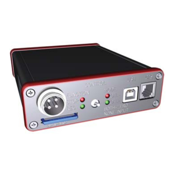
Titan CAI - Operation Rear Panel The Titan CAI Mini-Recorder rear panel incorporates two LED status indicators, a communications (COMM) port and DB9 input connectors: Status Indicators P (Power) – A green LED indicating that the CAI is ON. E (Error) – A red LED indicating that a sensor output has meet or exceeded the range for the confi... -
Page 11: Signal Flow
Titan CAI - Operation Signal Flow The diagram below shows the signal fl ow of the Titan CAI Mini-Recorder for a single input channel. The Titan ICP Mini-Recorder supports up to 16 channels at 2400 samples per second (Low Speed operation), or up to 60,000 samples per second (High Speed operation). -
Page 12: Calibration Modes
Titan CAI - Interface Calibration Modes Calibration for the Titan CAI Mini-Recorder can either be activated from the panel switch or under control from TCS. CAL+ and CAL- Calibration modes CAL+ and CAL- places a fi xed voltage into the input (if the calibration type for the channel is set to ‘VCal’). -
Page 13: Formatting Memory Cards
Titan CAI - Interface Formatting Memory Cards New SD memory cards must be formatted for the CAI Mini-Recorder prior to use. New memory cards should always be formatted in the CAI Mini-Recorder using the following procedure: 1. If a memory card is inserted, eject the card and power cycle the CAI. -
Page 14: Interface
Pinouts for the analog input connector, communications (COMM) port and GPS port are shown below. Analog Input Connector: Titan CAI Mini-Recorder provides up to 16 analog inputs on DB9F connectors. The connector pinouts are shown below. Channels 1 - 8... -
Page 15: Comm Port
Titan CAI - Interface COMM Port (currently not implemented) The pinout of the COMM port appears below. The POWER IN pin is internally confi gured at the factory for +5V, +12V or 0V. A label on the side nearest the COMM connector displays the POWER IN confi guration. -
Page 16: Features & Specifi Cations
Titan CAI - Specifi cations Features and Specifi cations Key Features • Supports multiple modes of operation: - Standalone recording up to 16 channels - Connected to a PC recording up to 16 channels • 24 bit analog conversion •... -
Page 17: Troubleshooting
Titan CAI - Troubleshooting Troubleshooting If you are having diffi culties confi guring, connecting or using your Titan device, refer to the troubleshooting section below. This section addresses common issues with the operation of Titan devices. If your specifi c issue is not addressed, please contact the factory for additional assistance. -
Page 18: Notes And Known Issues
Frequency Measurements 1. The Titan CAI supports a single frequency sensor on channel 8 only. 2. The frequency sensor input requires an input of 2Vpp or greater to function correctly. If there is a negative offset on the input signal, the signal may need to be boosted to register correctly. -
Page 19: Warranty & Repair
Malfunction If the unit fails to operate, or any fault develops, Mars Labs should be notifi ed, giving full details of the diffi culty, including model number and serial number. Upon receipt of this information, Mars Labs will provide service data and shipping instructions.
Need help?
Do you have a question about the Titan CAI and is the answer not in the manual?
Questions and answers