Table of Contents
Advertisement
Quick Links
Advertisement
Table of Contents

Summary of Contents for RATTIINOX CAD XACT-SEND 0 0 0000 Series
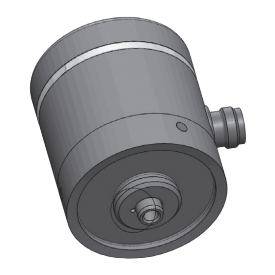
- Page 1 DOUBLE POSITION SENSOR MANUAL AND SAFETY INSTRUCTIONS CODE: XACT-SEND-0XX0-X0000...
- Page 3 INDEX 1. Scope 2. Description 2.1 Standards and ATEX marking 3. Operation 3.1 Setting procedure 4. Installation and maintenance 4.1 Intended use 4.2 Mounting and Installation 4.3 Maintenance and repair 4.4 Specific conditions of safe use (“X“) 5. Technical data 5.1 Safety ratings 5.2 Technical data 5.3 Electrical connections...
- Page 4 1. Scope This document is intended as an extract from the sensor installation and use manual. Additional information is offered in the sensor installation and use manual provided it does not conflict with the minimum information contained in this document. 2.
- Page 5 II 3G Ex ic IIC T6 Gc or II 3G Ex ic IIC T5 Gc II 3D Ex ic IIIC T85°C Dc or II 3D Ex ic IIIC T100°C Dc Marking required by Directive 2014/34 / EU (ATEX) Group II: product intended for surface environments, not mines Category 3: product suitable for zone 2 (G - gas) / zone 22 (D - dust) Manufactured for potentially explosive gas atmospheres Manufactured for potentially explosive dust atmospheres...
-
Page 6: Operation
Additional marking data: • Declared ambient temperature: from -10°C to +65°C, or from -10°C to +80°C. Temperature class: T6/T85°C with ambient temperatures up to +65°C. Temperature class: T5/T100°C with ambient temperatures up to +80°C. The ambient temperature range is specified in Certificate no. - Page 7 3.1 Open and closed valve limits setting procedure Using the appropriate programming accessory, it is possible to set the two detection limits of valve open and valve closed by following the following procedure (the setting of the limits must be carried out at room temperature): 1.
-
Page 8: Installation And Maintenance
4. Installation and maintenance 4.1 Intended use The device is approved for proper and intended use only. Failure to comply with these instructions will invalidate any guarantee and release the manufacturer from any liability. Use the device only in the specified environmental and operating conditions. -
Page 9: Technical Data
5. Technical data 5.1 Safety ratings Ui= 30V; Ii= 40 mA; Pi= 300 mW; Ci=200 nF; Li=20 μH 5.2 Technical data TECHNICAL DATA Supply voltage 10 ÷ 30VDC Maximum absorbed current without load 40 mA (@ Vin = 30V) Valve opening and closing Type: Open collector PNP transistor outputs Imax: 80mA... - Page 10 TABLE OF ABSORBED POWER WITHOUT LOAD VDC [V] IDC_[A] P [W] 0,04 0,04 0,04 0,04 0,96 0,04 5.3 Electrical connections CONNECTIONS V DC Max I Number Name Type Function [mA] Power Positive 10 ÷ 30 Supply Power Power Negative Supply Power Limits Input...
-
Page 11: Hazardous Area
REFERENCE FOR CONNECTOR ORIENTATION POS1 POS2 To program the sensor trip limits without the programmer, connect a N.O. button between the SET and Vin contacts. DIAGRAM FOR ATEX APPLICATIONS HAZARDOUS AREA SAFE AREA POWER SUPPLY ISOLATED REPEATER SET N VALVE POSITION SENSOR OUT1 OUT2... - Page 12 5.4 Mechanical connections and spare parts Install the correct needle and the correct spring on sensor shaft according to the following drawing. Part. code: Part. code: SPRING-0.60X9.1X06 SPRING-0.60X9.1X09 Use this spring Use this spring for CAD sizes: for CAD sizes: A12 (1/2”) A25 (1”) A19 (3/4”)
- Page 13 DETAIL C UPPER ANTIROTATION SOCKET FOR SPRING ATTENTION: PLEASE INSERT ANTIROTATION PORTION OF BOTH SIDE OF THE SPRING INSIDE RELATED SOCKET LOWER ANTIROTATION SOCKET FOR SPRING DETAIL D...
- Page 14 6. Tools 6.1 CAD Programmer CAD Programmer is a useful tool for fast and easy programming of CAD Double Position Sensor also while the valve is working. After connecting to the sensor, programming can be achieved just pushing 3 times the single pulsant: once to start programming, then for save closure point detection when actuator is on closed position and then a third time for saving the open position when the actuator is in correspondence of the open position.
-
Page 15: Cable Cross Section
6.2 Cable for double position sensor Cable for CAD Double Position Sensor, genuine cable to provide power supply to CAD Sensor, arrange remote programming via PLC and transmit open and close position of the actuator where sensor is installed. CONNECTION DIAGRAM 5 POLES FEMALE CABLE CROSS SECTION... - Page 16 RATTIINOX S.r.l. Via Mara, 44 I-22066 Mariano Comense (CO) T. +39.031.3551263 info@rattiinox.com www.rattiinox.com...
Need help?
Do you have a question about the CAD XACT-SEND 0 0 0000 Series and is the answer not in the manual?
Questions and answers