Table of Contents
Advertisement
Quick Links
Advertisement
Table of Contents

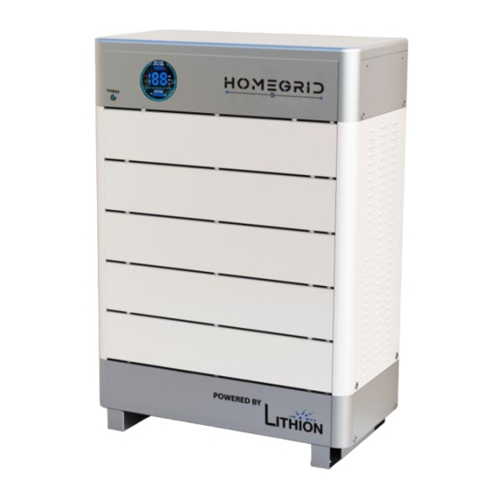
Summary of Contents for Lithion HOMEGRID Stack'd Series
- Page 1 Stack’d Series Reference Manual Rev 2.1 September 2022...
-
Page 2: Table Of Contents
Safety Precautions ......................3 1.1. General warnings......................3 1.2. Charge and discharge warnings..................4 1.3. Transportation warnings ....................5 1.4. Disposal of lithium batteries ................... 5 1.5. Before Connecting......................5 1.6. During Use ........................5 Introduction ........................7 2.1. Lithium iron phosphate Battery..................7 2.2. -
Page 3: Safety Precautions
1. Safety Precautions It is very important to read this user manual carefully before installing or using the battery. Failure to do so or to follow any of the instructions or warnings in this document can result in electrical shock, severe injury, or death. Installing the battery incorrectly can permanently damage the battery or render it inoperable. -
Page 4: Charge And Discharge Warnings
Do not paint any part of the battery; include any internal or external components. Do not drop, deform, impact, or cut with a sharp object. Do not power wash the battery or get it wet. Direct sunlight must be always avoided. -
Page 5: Transportation Warnings
1.3. Transportation warnings The battery must be transported in its original or equivalent package and in an upright position. If the battery is in its package, use soft slings to avoid damage. Do not stand underneath a battery on any sort of hoist. Keep hands and feet clear. :... - Page 6 Do not connect the Stack’d battery to any other type of battery. Do not connect the battery to an incompatible inverter. Do not attempt to disassemble the battery. In case of fire, only dry powder fire extinguisher can be used. Do not use liquid fire extinguishers.
-
Page 7: Introduction
2. Introduction The Stack’d Series lithium iron phosphate battery is an energy storage product developed and produced by HomeGrid. It can provide reliable power for several types of equipment and systems. The Stack’d Series is especially suitable for home energy storage systems. The Stack’d Series can do the following: 1. - Page 8 • The system will automatically manage charging and discharging and balance the current and voltage of each cell. • Flexible configuration, multiple battery modules can be internal for expanding voltage and Capacity. • Adaptative self-cooling reduced system noise. • The module has low self-discharge, up to 6 months without charging it on shelf, no memory effect, excellent performance of low discharge.
-
Page 9: Specifications
2.3. Specifications Figure 2.3.1 Assembled System with 5 Battery Modules Items Parameters Model PF5-LFP***00-2A01 Main Controller Module HG-MC100-200M2 Battery Module Type HG-FS48100-15OSJ1 Battery Module Chemistry LiFePO4 Battery Module QTY Nominal Capacity (Ah) Nominal Energy(kWh)*** 9.60 14.4 19.2 24.0 28.8 33.6 38.4 Nominal(V) 48.0... -
Page 10: Front Panel Display
2.4. Front Panel Display The front of the controller module includes a display that shows the status of the system. 4 5 6 7 9 10 Figure2.4.1 Controller module display Instructions Instructions Animated streamline Battery state of health (SOH) Discharge power Numerical percentage Charging power Number of modules... - Page 11 2 3 4 Figure2.4.2 Controller module display details Instructions Instructions Power switch Hardware version Current voltage level Energy throughput Software version Capacity of a new battery Power switch The power switch turns the entire system on and off. Display screen Display screen: Displays the State of Charge (SOC), State of Health (SOH), charging/discharging power, alarm fault indication, charging and discharging status, and overall system status.
- Page 12 Status code Status code: The code will only be displayed if a fault occurs. If the system is operating normally the code will not be shown. The alarm codes are shown in the table below: Numerical Numerical Alarm indication Alarm indication value value Normal...
-
Page 13: Control Module Switches And Connectors
2.5. Control Module Switches and Connectors 11 12 13 14 Figure2.4.3 Control Module Terminals and Connectors Instructions Instructions Inverter protocol selection switch Parallel communication port B Imped. SET (Reserved) Parallel communication port A Controller Address Dial Switch Inverter CAN communication port Dry Contact (Reserved) Inverter RS485 communication port Inverter CAN/ RS485communication port... - Page 14 Controller address dial switch The Controller Address Dial Switch sets the address of the controller module of a given stack. It is possible to have up to 15 stacks connected in parallel and controlled by one Master Controller. The Master Controller should have its address set to 1 as shown in the table below. The slave controllers should be set to address 2, then 3 and so on.
- Page 15 Dial Code Switch Position Inverter Protocol Definition Setting Monitoring Software setting mode ZRGP Studer_Xtender Sofar_LV Solis_LV Goodwe_LV Victron_color_control SMA_LV Sermatec_HV Reserved Growatt_SPF Li_PLUS Schneider Gateway SOL-ARK_LV Reserved Reserved Reserved SUNSYNK Growatt_SPH&SPA Reserved Reserved Reserved Reserved Reserved Reserved Reserved Reserved Page 15 Chapter 2: Introduction...
- Page 16 GreenCell Reserved Must Dial Code Switch Position Inverter Protocol Definition Setting Reserved Reserved Reserved Reserved Find the number of modules attached to the system. Inverter CAN/RS485 communication port Inverter CAN/RS485 communication port: (3.81mm port) follows the CAN and RS485 protocols. The system master uses this interface to communicate with some external inverters and other equipment.
- Page 17 Port definitions RJ45Pin Function RS485-B RS485-A RS485-GND CAN-L 123456 CAN-H CAN-GND RS232 communication port RS232 communication port (RJ45 Port) with a baud rate of 9600 bps for debugging or service. Port definitions RJ11 Pin Function NC (No connect) NC (No connect) RS232-GND RS232-TX RS232-RX...
- Page 18 Rear panel RS485 communication port: follows CAN protocol and RS485 protocol. For the output system information, the system master uses this interface to communicate with External inverter PC and other equipment. Port definitions RJ45 Pin Function RS485-B RS485-A RS485-GND NC (No connect) NC (No connect) RS485-GND RS485-A...
-
Page 19: Battery Module Controls
Rear panel Link A / Link B communication port Link A / B communication port:(RJ45 port) the definition of link A and B on the rear panel of the interface main control module is the same. This RS485 interface is used for parallel communication between the main control modules, and up to 15 devices can be connected in parallel. - Page 20 Port definitions RJ11 Pin Function NC (NO CONNECT) RS232-GND RS232-TX RS232-RX RS232-GND NC (NO CONNECT) Address dial switch Each battery module must have its own ID. The modules should be numbered from 1 to N where N is the number of modules. Module 1 should be the top module in the stack and module N the bottom one.
-
Page 21: How To Use The Monitoring Software Ems Tools
3. How to use the Monitoring Software Ems Tools 3.1. Monitoring Software Ems Tools connection ConnecttheRS232interfaceofthebatterytothecomputerusingtheRS232communicationli ne (this accessory is an optional accessory, need to be purchased separately from the manufacturer). Unzip the package file of the Monitoring Software Ems Tools in the same file directory. - Page 22 Select the serial port number in the EMS low voltage version of the Monitoring Software EMS tool. The default baud rate is 9600. Click the open com and monitor open buttons. Series Port Figure3.1.5 Monitoring Software Ems serial port settings The corresponding functions can be selected through the navigation bar of the Monitoring Software EMS.
- Page 23 Navigation bar Password for Parameter Setting Figure3.1.7 Monitoring Software Cluster data acquisition The configuration parameter interface displays the manufacturer identification, software version, hardware version, production serial number, temperature quantity and module battery quantity of a cluster in real time. Figure3.1: Monitoring Software Cluster Matching parameters NOTE: ●...
-
Page 24: Matching The Controller To The Inverter
4. Matching the Controller to the Inverter 4.1. Supported brands A Stack’d system must be connected to an inverter to convert the DC power from the batteries to AC current to run things like lights, appliances, and HVAC units. At other times, the inverter will provide DC power to recharge the batteries. - Page 25 Inverter Communication mode Brand Type Protocol Version SPF12KT HVM V1.22 RS485 Growatt SPH3000 V1.26 Studer Xtender-XTH-8000-48 V1.0.3 Xcom-CAN Sofar HYD5000-ES V6.0 Solis RHI-5K-48ES V1.2 Goodwe GW5048-EM V1.5 Victron MultiPlus-II V6.0 DEYE SUNSYNK-5K-SG01LP1 V1.5 S16.0H-12 V2.0 Sermatec SMT-5K-TL-UN V1.2 Schneider Conext Gateway V2.0 Li_PLUS ZR Standard...
-
Page 26: Connection With Inverter
4.3. Connection with the inverter This section describes how to connect the Controller to inverters. Manufacturers may upgrade their products resulting in hardware communication interface changes. If communication is not possible in the application according to the following wiring method, please contact us. The CAN/RS485 communication port of HomeGrid is connected to the communications interface of inverter. -
Page 27: Safe Handling Of Lithium Batteries Guide
5. Safe handling of lithium batteries Guide 5.1. Schematic Diagram of Solution Figure5.1.1.Schematic diagram of solution 5.2. Unpacking the system Be careful when unpacking the system. Each module is heavy and requires at least two people to lift. Figure5.2.1. Side view of the entire system Page 27 Chapter 5: Safe handling of lithium batteries Guide... -
Page 28: Precautions Before Installation
5.3. Precautions before installation Before installation, be sure to read the contents in Chapter 1 Safety Precautions, which is related to the operation Safety of installation personnel, please pay attention to. 5.4. Tools The following tools are required to install the battery pack: Wire cutter Cable clamp Screwdriver... -
Page 29: Installation
6. Installation 6.1. Package Items Unpacking and check the Packing List: 1)PACKING LIST After receiving the system, please check to ensure that all the following components are not lost or damaged Battery terminal ×2 ESSsystem×1 Positive negative terminals ×2 M6*10x6 M8*16x2 Main control fixing bracket×2 M3*12x15... -
Page 30: Installation Location
Positive Busbar Negative Busbar 3) Communication connecting line between system and inverter (Optional) 6.2. Installation Location Make sure that the installation location meets the following conditions: 1. The location drains properly, there are no puddles. 2. The floor is flat and level, and capable of supporting the weight of the system. (See Section 2.3) 3. - Page 31 (1) Place the system base at the bottom (2) Stack the battery modules one by one. The guide pins will make sure that the connectors mate properly. (3) Finally, place the main control module at the top of the system (4) When the stack is complete set the battery module addresses as described in Section 2.
- Page 32 (5) Turn on the power switch on the controller module. Observe that the display screen has no alarm protection status, the number of battery modules has no loss and flicker, and the system parameters and status display are normal. The display will indicate the number of battery modules that the controller has found.
- Page 33 control side plate. NOTE: ●Before starting the system, the operator should strictly check the connection terminal to ensure that the terminal is firmly connected, check whether the battery address is set correctly, and whether the inverter switches are in the off state. Do a good job in safety protection and turn on the inverter in the following order. The battery module bottom insulation skin should be removed.
- Page 34 Figure5.4. Schematic diagram of parallel solution Note: after installation please contact the supplier to register online for full warranty. Page 34 Chapter 7: Trouble Shooting Steps...
-
Page 35: Trouble Shooting Steps
7. Trouble Shooting Steps 7.1. Problem determination based on 1) Whether the battery can be turned on or not. 2) If battery is turned on, check the red light is off, flashing or lighting. 3) If the red light is off, check whether the battery can be charged/discharged or not. 7.2. -
Page 36: Storage, Transportation And Emergency Situations
8. Storage, Transportation and Emergency Situations 8.1. Storage Recharge and maintain the battery pack regularly every three months to ensure the battery is in the best condition. 8.2. Emergency Situations Leaking Batteries If the battery pack leaks electrolyte, avoid contact with the leaking liquid or gas. If one is exposed to the leaked substance, immediately perform the actions described below. - Page 37 Address: 1350 Wigwam Parkway, Henderson, NV 89074 Email: info@homegridenergy.com Official web site: www.homegridenergy.com...
Need help?
Do you have a question about the HOMEGRID Stack'd Series and is the answer not in the manual?
Questions and answers