Table of Contents
Advertisement
Advertisement
Table of Contents

Summary of Contents for HAWEKA AXIS4000
- Page 1 Operating instructions Electronic wireless camera system for axle measurement on commercial vehicles (Translation of the original manual) Kokenhorststraße 4 • D-30938 Burgwedel • Tel. +49 (0)5139/8996-0 • Fax +49 (0)5139/8996-222 • www.haweka.com • info@haweka.com GEB 001 091...
-
Page 3: Table Of Contents
Preparations for measurement ..................25 Front axle measurement ....................26 Preparatory measures on the vehicle ..................26 Specifying vehicle data in the AXIS4000 program ..............27 Setting up the reflectors (scale setup) ..................28 9.3.1 Fitting the magnetic feet onto the vehicle ....................28 9.3.2... - Page 4 10.2.2 Adjusting when out of square ......................... 40 11 Protocol, vehicle overview ................... 41 12 The AXIS4000 user reference database ..............43 12.1 Creating new vehicles in the database ..................43 12.2 Using the user reference database ..................44 13 Trailers and articulated trailers ..................45 13.1 Preparatory measures for measuring articulated trailers ............
-
Page 5: General Safety Instructions
YSTEM General safety instructions 1.1 Duty of care of the operator The AXIS4000 wheel alignment system has been designed and con- structed according to pertinent, mandatory harmonised norms. It therefore conforms to the latest status of technology and offers the maximum degree of safety and reliability during operation. -
Page 6: Suspension Terminology
The total toe is the dimension between the centre-line of the tyres. In the case of twin-wheel axles, the measurement is taken from centre-line to centre-line of the twin wheels. This has a crucial effect on the steering characteristics of the vehicle in bends. An uncorrected toe enables higher speeds in bends. HAWEKA Wheel Alignment –AXIS4000... -
Page 7: Measurement Sizes For Wheel Alignment
The castor designates the angle of the king pin to the vertical either to the front or rear. The castor angle affects the directional steering sta- bility. Positive castor: high steering and holding forces Negative castor: poor steering return. HAWEKA Wheel Alignment –AXIS4000... -
Page 8: Transporting The Wheel Alignment System
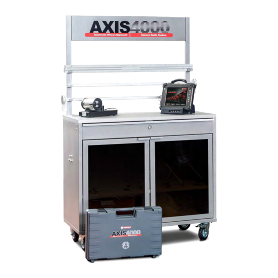
AXIS4000 W HEEL LIGNMENT YSTEM Transporting the wheel alignment system 3.1 Dimensions and weight Illustration: AXIS4000 Standard (#924 000 030) Length x Width x Height Transport weight: (cm) (kg / gross) AXIS4000 PRO 924 000 010 140 x 100 x 70... -
Page 9: Product Description
Product description AXIS4000 Wheel Alignment System 924 000 010 / 030 / 050 Date: 12 / 2017 Subject to technical amendment. Version 5.1 Graphics: HAWEKA AG / D-30938 Burgwedel Reproduction in any form is not allowed. HAWEKA Wheel Alignment –AXIS4000... -
Page 10: Proper Use
LIGNMENT YSTEM 4.1 Proper use • The AXIS4000 wheel alignment system has been developed to perform suspension meas- urements on motor vehicles, trailers, semi-trailers and agricultural towing vehicles. • It is intended exclusively for rapid measurement of suspension geometry. For the front axle and articulated axles:... -
Page 11: Design Of The Camera Measurement Head
The camera shaft is permanently mounted onto the 3-arm star. It was adjusted and calibrated after mounting. If (e.g. after a fall) you suspect that the camera shaft is not vertical to the 3-arm star anymore, please contact your supplier! HAWEKA Wheel Alignment –AXIS4000... -
Page 12: Technical Data
100 - 240 Volt Turning plates Load-bearing capacity 6 to. / each 4.4 PC system requirements for the AXIS4000 Required operating system: Windows XP, Windows 7, 8.1, 10 Necessary minimum hardware requirements: Processor: Pentium IV – AMD Athlon 1 GHz RAM: 512 MB (Windows XP) / 2048 MB (Windows 7, 8.1, 10) -
Page 13: Equipment
AXIS4000 W HEEL LIGNMENT YSTEM Equipment 5.1 Parts list - AXIS4000 basic version 2 pcs. Camera measurement heads Item No. 924 001 000 6 pcs. Magnetic holder (100 mm) Item No. 913 027 004 6 pcs. quick-change system Item No. 913 027 006 2 pcs. - Page 14 1 pc. Radio Server Unit incl. USB cable Item No. 924 001 160 1 pc. Camera charging station Item No. 924 001 034 4 pcs. Reflectors Item No. 924 001 025 4 pcs. Tripod stands Item No. 913 052 024 HAWEKA Wheel Alignment –AXIS4000...
- Page 15 Item No. 913 052 077 1 pc. System stands (only for 924 000 010) Item No. 900 008 200 1 pc. USB-Stick 1 pc. Operating instructions 1 pc. Aluminium case Program AXIS4000 for cameras, reflectors and transmitter HAWEKA Wheel Alignment –AXIS4000...
-
Page 16: Axis4000 Optional Accessories
AXIS4000 W HEEL LIGNMENT YSTEM 5.2 AXIS4000 optional accessories 1 pc. Equipment trolley for storage and transport Item No. 924 001 035 1 pc. Handheld PC Item No. 924 001 047 2 pcs. Additional turning plates for second articulated vehicle axle Item No. -
Page 17: Initial Commissioning
LIGNMENT YSTEM Initial commissioning The following measures are required when using the wheel alignment system for the first time: Assemble the AXIS4000 components Install the software and FM transmitter under Windows Setup the software. 6.1 Assembling the reflector stand One reflector stand comprises the following components:... -
Page 18: Installing Software Under Windows
The driver for the FM transmitter is usually added automatically to the system on your computer when the AXIS4000 program is installed. If the FM transmitter is connected to a free USB port on the PC after installation, the new hardware will be detected and integrated into the system. - Page 19 Win- dows XP. Read the information and continue with the installation. To do this, select: Continue installation (Fig. 7) • After installation, remove the USB-Stick from the PC. (Fig. 7) HAWEKA Wheel Alignment –AXIS4000...
-
Page 20: The Axis4000 Program
7.1 Setting up the software • Start the program. Under Windows select: START –ALL PROGRAMS – HAWEKA – AXIS4000 and click on the pro- gram entry AXIS4000. (Fig. 8) After the program has started, select the "Settings" option for the first basic setting. -
Page 21: Overview Of The Program Settings Screen
Pressing the Select language button will give you the option of having the menu and all in- structions in a language of your choice. (Fig. 10) All settings must be confirmed by the SAVE button. (Fig. 10) HAWEKA Wheel Alignment –AXIS4000... -
Page 22: Interface
(Fig. 12) The display flashes between yellow and red. The program is at- tempting to connect with the cameras. (Fig. 13) (Fig. 13) Display is green: a connection is established to the camera. (Fig. 14) (Fig. 14) HAWEKA Wheel Alignment –AXIS4000... -
Page 23: Default Side Of Steering
All suspension measurements are saved in a proto- col/report file. The preset directory path is: My_Documents\User\Name\Applications\Haweka\ (Fig. 21) AXIS4000\Database (Fig. 21) To change the storage location, click the "Folder" button: To restore the standard path, click the "Back" button: HAWEKA Wheel Alignment –AXIS4000... -
Page 24: Extended Settings
(Fig. 24) With the help oft the user database, own vehicles can be created for the comparision of the actual and the nomi- nal data. For the application of the user database see Page 43 Point 12. HAWEKA Wheel Alignment –AXIS4000... -
Page 25: Preparations For Measurement
Note the manufacturer's specifications for different loads in order to simulate driving conditions. • Remove the wheel nut covers and/or hubcaps • Clean the wheel rims between the wheel nuts so that the magnetic feet ensure correct positioning of the camera holder on the rim. HAWEKA Wheel Alignment –AXIS4000... -
Page 26: Front Axle Measurement
• Pull the attachment bolt of the camera up slightly, and push the camera onto the camera shaft until it clicks into the groove on the shaft. • Now lock the camera onto the shaft by gently tightening the attachment bolt. (Fig. 28) (Fig. 28) HAWEKA Wheel Alignment –AXIS4000... -
Page 27: Specifying Vehicle Data In The Axis4000 Program
The Radio Server Unit is connected to the PC and the PC is switched on. (see Installation Point 6.4) The AXIS4000 program has been started and is showing the start screen. • Select the Start measurement button. • Enter vehicle data and select the vehicle type using the quick selection function. -
Page 28: Setting Up The Reflectors (Scale Setup)
There are 2 reflector stands each with 2 reflectors. THE REFLECTORS ON THE MAGNETIC FEET ARE REMOVED TO SETUP THE REFLECTOR STAND. (Fig. 33) • Assembly is carried out by putting together the reflec- tor stand, tripod stands and reflectors. HAWEKA Wheel Alignment –AXIS4000... - Page 29 BE MOVED AGAIN FROM THEIR POSI- TIONS FOR THE DURATION OF MEAS- (Fig. 36) UREMENT. If the position of the reflector stands is altered during measurement, they must be re-aligned. Meas- urement can then be continued from the last measurement point. HAWEKA Wheel Alignment –AXIS4000...
-
Page 30: Measuring The Camber
(Fig. 39) plays the newly set value in the AFTER column. (Fig. 40) The BEFORE column means measured values before the setting. The AFTER column means: measured values after the setting (Fig. 40) (Fig. 41) HAWEKA Wheel Alignment –AXIS4000... -
Page 31: Steering Gear Middle Position
The measured value is displayed as soon as the work steps have all been completed. • The Continue button changes the program back to the overview screen for the selected axle and dis- plays the ACTUAL measured value. (Fig. 45) HAWEKA Wheel Alignment –AXIS4000... -
Page 32: Adjusting The Steering Gear
After adjustments are complete, settings are con- cluded with the Continue button. The program (Fig. 47) changes back to the overview screen for the select- ed axle. The newly set value appears under the "Af- ter" column. (Fig. 48) (Fig. 48) HAWEKA Wheel Alignment –AXIS4000... -
Page 33: Measuring The Total Toe And Single Toe
NOMINAL values. (Fig. 51) • If the toe values measured lie outside the permitted tolerance for NOMINAL values, the vehicle geometry must be adjusted. This is done by selecting the adjust button for the toe. HAWEKA Wheel Alignment –AXIS4000... -
Page 34: Adjusting The Toe
If the toe value is needed in degrees, then the display can be changed from [mm] to [degrees]. (Fig. 54) On this topic, please refer to Point 7.2.8 Ex- tended settings. Value in degrees/minutes (Fig. 54) HAWEKA Wheel Alignment –AXIS4000... - Page 35 If the toe value is needed in degrees, then the display can be changed from [mm] to [de- grees]. (Fig. 58) On this topic, please refer to Point 7.2.8 Ex- tended settings. (Fig. 57) (Fig. 58) HAWEKA Wheel Alignment –AXIS4000...
-
Page 36: Castor, Kpi, Relative Steering Angle And Max. Turn Angle
Once the procedure is completed, the measured values recorded will appear after a brief pause. (Fig. 62) • The Continue button changes the program back to the overview screen for the selected axle and dis- plays the ACTUAL value measured. (Fig. 62) HAWEKA Wheel Alignment –AXIS4000... -
Page 37: Adjusting The Maximum Turn Angle
(Fig. 63) The Continue button changes the program back to the overview screen for the selected axle and displays the newly measured values in the AFTER column. (Fig. 64) (Fig. 64) HAWEKA Wheel Alignment –AXIS4000... -
Page 38: Rear Axle Measurement
• The Continue button changes the program back to the overview screen for the selected axle and dis- plays the newly measured value in the AFTER col- umn. (Fig. 67) (Fig. 67) HAWEKA Wheel Alignment –AXIS4000... -
Page 39: Toe / Inclination
(Fig. 71) If the toe value is needed in degrees, then the display can be changed from [mm] to [degrees]. On this topic, please refer to Point 7.2.8 Ex- tended settings. (Fig. 71) HAWEKA Wheel Alignment –AXIS4000... -
Page 40: Adjusting When Out Of Square
The program changes to the overview screen for the new third axle. The procedure for all further axles is dependent on the type of axle and is the same as described for axle 1 (steering axle) and axle 2 (rigid axle). (Fig. 74) HAWEKA Wheel Alignment –AXIS4000... -
Page 41: Protocol, Vehicle Overview
Use the Save button when work is finished to save the (Fig. 78) completed measurements. (Fig. 78) Use the Print button to print out the recorded data as a (Fig. 79) protocol/report on an installed printer. (Fig. 79) HAWEKA Wheel Alignment –AXIS4000... - Page 42 (Fig. 81) If the data record for a measuring session has been saved, you will be able to carry out further measurements on this vehicle days later. To do this, select the Continue button. HAWEKA Wheel Alignment –AXIS4000...
-
Page 43: The Axis4000 User Reference Database
YSTEM 12 The AXIS4000 user reference database You can use this additional module for the AXIS4000 wheel alignment program to enter and save default target values for vehicle geometry data. You can use this additional module to carry out a nominal/actual value comparison, during or after measurement. -
Page 44: Using The User Reference Database
(Fig. 88) • To leave the nominal data screen and con- tinue with measuring, click on the Cancel symbol on the bottom right side. (Fig. 89) (Fig. 89) HAWEKA Wheel Alignment –AXIS4000... -
Page 45: Trailers And Articulated Trailers
AXIS4000 W HEEL LIGNMENT YSTEM 13 Trailers and articulated trailers If the AXIS4000 is only available in a basic version, then you will require an upgrade kit to measure truck trailers and semi-trailers. (Fig. 90) (Fig. 90) The upgrade kit for measuring trailers and articulated trailers, Item No. 923 000 001 comprises: A.) 1 x king pin adapter Ø... -
Page 46: Setting Up The Reflector Stands For Articulated Trailers
The procedure for this is as described under Point 9.3.2 Page 30. Both reflector stands must be optically aligned in such a (Fig. 93) way that they stand at rectangles to the long axle of the vehicle. (Fig. 94) HAWEKA Wheel Alignment –AXIS4000... -
Page 47: Setting Up The Reflector Stands
LIGNMENT YSTEM Articulated trailers 13.2.1 Setting up the reflector stands • Use the quick selection option in the AXIS4000 program to select a trailer with the right number of axles. The program changes to entry of vehicle data. (Fig. 95) •... -
Page 48: Aligning The Vehicle Axle On The Drawbar
Now the vehicle axle is aligned against the drawbar until the values shown for both sides are the same. (Fig. 101) • Use the parking brake to lock the vehicle wheels on the axle. • End the procedure with the Continue" button. (Fig. 101) HAWEKA Wheel Alignment –AXIS4000... -
Page 49: Examining The Trailer Coupling Ring In Relation To The Vehicle Centre-Line
Now the king pin adapter with reflector stand is (Fig. 104) pushed onto the coupling adapter and screwed tight using the knurled screw. (Fig. 106) • The reflectors are attached to the reflector stand on the right and left sides. (Fig. 105) (Fig. 106) HAWEKA Wheel Alignment –AXIS4000... -
Page 50: Setting Up The Rear Reflector Stand
• The vehicle centre-line is now defined for the follow- ing measurements and the reflector setup is conclud- ed with the Continue button. (Fig.108) HAWEKA Wheel Alignment –AXIS4000... - Page 51 The reflector stand is fitted with the aid of the king pin adapter and the coupling adapter (as described for trailers) and a 2-axle articulated trailer is selected in the program. (Fig. 112) All other work steps are described under Point 12.2.1. (Fig. 112) HAWEKA Wheel Alignment –AXIS4000...
-
Page 52: Vehicles With Two Steerable Front Axles
• The axles can be adjusted to the necessary value using the displays. (Fig. 116) • Then press the "Continue" button to return to the second axle overview. (Fig. 116) HAWEKA Wheel Alignment –AXIS4000... -
Page 53: Taking Into Account Floor Inclination
AXIS4000 W HEEL LIGNMENT YSTEM 15 Taking into account floor inclination The AXIS4000 can take account of different floor inclinations for each axle during measurement. (Fig. 117) (Fig. 117) Observe the following steps: • After selecting the vehicle, tick the test floor incli- nation box on the vehicle data overview screen and select the new button "Floor inclination"... - Page 54 After measuring floor inclination for all axles, press the "Continue" button. The program changes back to the vehicle data screen for the selected vehicle and the meas- urement can be conducted in the normal se- quence. HAWEKA Wheel Alignment –AXIS4000...
-
Page 55: Special Rims
IF YOU SWAP VEHICLE AXLES DURING MEASUREMENT (BY CLICKING THE BUT- TON 1 / 2 / 3 ETC.), YOU WILL HAVE TO CARRY OUT RUN-OUT COMPENSATION AGAIN. (Fig. 126) HAWEKA Wheel Alignment –AXIS4000... -
Page 56: Maintenance
Only use the charging unit supplied to recharge the batteries in the camera measurement heads. This unit conforms with European safety standards and is especially designed for the batteries used in the AXIS4000 wheel alignment system. HAWEKA Wheel Alignment –AXIS4000... -
Page 57: Fault-Finding And Correction
• Measurement head align- • Check by carrying out a run- ment incorrect out test of the wheel align- ment clamp and re-measuring the toe, if necessary contact the Service department HAWEKA Wheel Alignment –AXIS4000... -
Page 58: Appendix
AXIS4000 W HEEL LIGNMENT YSTEM 19 Appendix 19.1 Measurement report for vehicle measurement HAWEKA Wheel Alignment –AXIS4000... -
Page 59: Ec Conformity Declaration
DIN EN 60068-2-31, EC Design changes that affect the technical data specified in the operating instructions as well as the proper, intended use of the system render this conformity declaration invalid! Dirk Warkotsch Burgwedel, 04.12.2017 (Signature) HAWEKA Wheel Alignment –AXIS4000... -
Page 60: Haweka Ag
HAWEKA AG Kokenhorststr. 4 D-30938 Burgwedel +49 (0)5139-8996-0 +49 (0)5139-8996-222 www.haweka.com Info@haweka.com...
Need help?
Do you have a question about the AXIS4000 and is the answer not in the manual?
Questions and answers
The unit has power but the screen is blank
The screen may be blank on the HAWEKA AXIS4000 despite the unit having power due to the following reasons:
1. No connection to the cameras: This could be caused by:
- Low battery power in the camera measurement heads. Recharge using the supplied charging unit.
- Incorrect interface connection settings in the program. Set the interface to AUTO in the settings.
- No or incorrect radio channel for camera connection. Try connecting using a different radio channel.
- Missing USB driver for the receiver. Install the USB driver from the provided USB stick.
2. Camera not detecting signals from reflectors: This could be due to:
- Dirty or damaged reflectors. Clean or replace them.
- Dirty rim surfaces. Clean the rim surfaces.
If these issues persist, further troubleshooting may be required.
This answer is automatically generated