Table of Contents
Advertisement
SMS Controller
TMN-5000i Hardware User Manual
(Ver.1)
Copyright 2001-2018, TCAM Technology Pte Ltd. All Rights Reserved.
This document (TMN-5000i-V1) contains information that is proprietary to TCAM Technology Pte
Ltd. No part of this document may be copied, or reproduced in any form or by any means, or
transferred to any third party without prior written consent of TCAM Technology Pte Ltd. The content
of this document may be revised without prior notice.
1
TMN-5000i-V1
TMN-5000i Hardware User Manual (Ver.1)
Advertisement
Table of Contents

Summary of Contents for TCAM TMAS TMN-5000i
- Page 1 Ltd. No part of this document may be copied, or reproduced in any form or by any means, or transferred to any third party without prior written consent of TCAM Technology Pte Ltd. The content of this document may be revised without prior notice.
-
Page 2: Table Of Contents
Table of Contents Introduction ..............................3 Product Overview ............................3 Accessories ..............................4 LED Indicators ...............................5 TMN-5000i Key Features and Specifications ....................6 Hardware Configuration ..........................7 Step 1: Insert SIM Card .........................7 Step 2: Connect Backup Battery ......................8 Step 3: Connect Input/ Output (I/O) ....................8 Step 4: Install Antenna .........................9 Step 5: Connect Programming Cable to PC ..................9 Step 6: Configure TMN-5000i on PC .....................9... -
Page 3: Introduction
Introduction This document will briefly describe the product features and specifications of SMS Controller - TMN-5000i. It will also covers a step-by-step guide to configure the device. For more information on how to use the TMAS PC Manager Software, please refer to the attached TMAS PC Manager Quick User Guide, or download the user guide from our website’s product page. -
Page 4: Accessories
Accessories Figure 1 TMN-5000i Unit Figure 2 3G Antenna Standard package contains: TMN-5000i Unit x 1 Consists of an on-board modem, a SIM card holder, 2 pieces of 10 ways pluggable terminal block and a polycarbonate plastic white casing 3G Antenna x 1 ... -
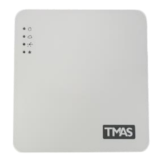
Page 5: Led Indicators
LED Indicators Indication Description No AC power or backup battery power. Power LED TMN-5000i is powered. On-board modem is offline. No SIM card inserted, or no antenna is plugged 500ms ON, 500ms OFF in, or network search in progress, or network login in progress. -
Page 6: Tmn-5000I Key Features And Specifications
TMN-5000i Key Features and Specifications Hardware Features No. of Digital Inputs (Dry contact or TTL) No. of Digital Outputs (Open collector drive) Power Adapter (240V 0.6A) AC/DC (12V 2A) Real Time Clock Yes (CR2032 battery is included) On-board Modem Cinterion EHS5-E Antenna Interface SMA (50ohm) female Backup Battery... -
Page 7: Hardware Configuration
Hardware Configuration This section will guide you step-by-step to setup your TMN-5000i for the first time. You may find a video guide online on our website’s product page. Step 1: Insert SIM Card There are a total of 6 locks (circled in red colour) as shown below in the Figure 6. From the side groove (shown below in the Figure 7), use a flat screwdriver to pry open the casing. -
Page 8: Step 2: Connect Backup Battery
Next, locate the SIM card holder which is underneath the printed circuit board (as shown below in the Figure 8). Insert your SIM card with its chip facing up. Push it inward until you hear a click sound. Figure 8 Locations of the SIM Card Holder and Backup Battery Power Socket To extract your SIM card, push it inward again until you hear a click sound, and then release your finger. -
Page 9: Step 4: Install Antenna
Repeat the above same method to connect for your output device. Step 4: Install Antenna Locate a gold-coloured female antenna socket and plug it with the antenna provided. Step 5: Connect Programming Cable to PC Before you can deploy your TMN-5000i, you will need to configure it on TMAS PC Manager via serial programming. -
Page 10: Alarm Control And Output Control
Alarm Control and Output Control I/O Terminals There are a total of 8 digital inputs (DI0 to DI7). The input terminals can interface with +5V TTL or dry contact digital input. The normal state can be configured to NC or NO state on TMAS PC Manager. - Page 11 Appendix A TMN-5000i Interface Panel TMN-5000i-V1 TMN-5000i Hardware User Manual (Ver.1)
-
Page 12: Technical Support
Technical Support For any sales and technical enquiries, please contact your local sales representatives or TCAM Technology Pte Ltd. 2 Kaki Bukit Ave 1 #05-04 Singapore 417938 Tel: 65-67461930 Fax: 65-67461938 Company Website: https://www.tcam.com.sg For sales enquiries, please email to enquiry@tcam.com.sg For technical enquiries, please email to support@tcam.com.sg...
Need help?
Do you have a question about the TMAS TMN-5000i and is the answer not in the manual?
Questions and answers