Advertisement
Active Device
ADM
Ring
PRODUCT
ADM
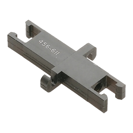
Single-Position
Bulkhead Receptacle
Figure 1
1. INTRODUCTION
This instruction sheet covers assembly and installation
of OPTIMATE DNP fiber optic ADM 228043-1,
Receptacle 228042-1, and Active Device Ring
501084-1. Refer to Figure 1.
Dimensions in this instruction sheet are in metric
NOTE
units [with U.S. customary units in brackets].
Figures are not drawn to scale.
i
Reasons for reissue of this instruction sheet are
provided in Section 5, REVISION SUMMARY.
Note: Not to Scale
1.65 [.065]
(Horizontal Mounting Only)
© 2012 Tyco Electronics Corporation, a TE Connectivity Ltd. company
All Rights Reserved
*Trademark
TE Connectivity, TE connectivity (logo), and TE (logo) are trademarks. Other logos, product and/or company names may be trademarks of their respective owners.
OPTIMATE* Dry Non-Polish (DNP) Fiber Optic
Active Device Mount (ADM) 228043-1, Receptacle
228042-1, and Active Device Ring 501084-1
Single-Position
Bulkhead Receptacle
MATING PACKAGE
TO-18, TO-46, TO-52
Active Device
Single-Position Plug Assembly
228087-1
Single-Position Plug Assembly
228087-1
ADM PC Board Layout
1.27 [.050] Typ
2.39 [.094] Dia
(4 Places)
3.81 [.150]
13.97 [.550]
TOOLING ASSISTANCE CENTER 1-800-722-1111
PRODUCT INFORMATION 1-800-522-6752
2. DESCRIPTION
The ADM connects single fibers to various active
devices (sources and detectors). The ADM houses the
active devices and mates with the single-position plug
assembly listed in Figure 1. The active device ring fits
onto the active device and is used to center it in the
bore of the ADM.
The receptacle is used with a single-position plug
assembly for fiber-to-fiber connections and joining two
single-position plugs. Refer to instruction sheet
408-2974 for information on the single-position plug
assembly.
3. ASSEMBLY AND INSTALLATION
The following methods are suggested for installing the
ADM and receptacle. The procedure used depends on
specific manufacturing and assembly requirements.
3.1. ADM
1. Prepare the pc board using the recommended
footprint dimensions given Figure 2. Maximum
panel thickness is 1.575 mm [.062 in.].
2. Slip the active device ring around the active device,
and insert it into the rear of the ADM. Make sure
that the tab on the device is in the slot of the ADM.
See Figure 3.
3. Insert the active device leads into the pc board.
4. Secure the ADM to the pc board using two No.
2-56 screws and nuts (customer supplied). The
ADM is typically mounted horizontally (as shown in
Figure 3) or vertically.
0.635 [.025] Dia Holes
1.27 [.050] Dia Pads
0.635 [.025] Wide Traces
6.35
[.250]
6.98 [.275]
Figure 2
This controlled document is subject to change.
For latest revision and Regional Customer Service,
visit our website at www.te.com
Instruction Sheet
408-9234
02 MAY 12 Rev B
1.27 [.050]
10.16
[.400]
PC Board Edge
1 of 2
Advertisement
Table of Contents

Summary of Contents for TE OPTIMATE 228043-1
- Page 1 All Rights Reserved PRODUCT INFORMATION 1-800-522-6752 For latest revision and Regional Customer Service, *Trademark visit our website at www.te.com TE Connectivity, TE connectivity (logo), and TE (logo) are trademarks. Other logos, product and/or company names may be trademarks of their respective owners.
- Page 2 408-9234 3.2. Receptacle 5. Solder the active device leads to the pc board. 6. Mate the plug assembly to the ADM. 1. Cut the panel using the recommended cutout dimensions given in Figure 4. 2. Install the receptacle in the panel cutout, and Typical ADM Horizontal (Shown) PC Board Installation secure it using the two No.
Need help?
Do you have a question about the OPTIMATE 228043-1 and is the answer not in the manual?
Questions and answers