Table of Contents
Advertisement
Quick Links
Advertisement
Table of Contents

Related Manuals for ERICHSEN 518 USB

Summary of Contents for ERICHSEN 518 USB
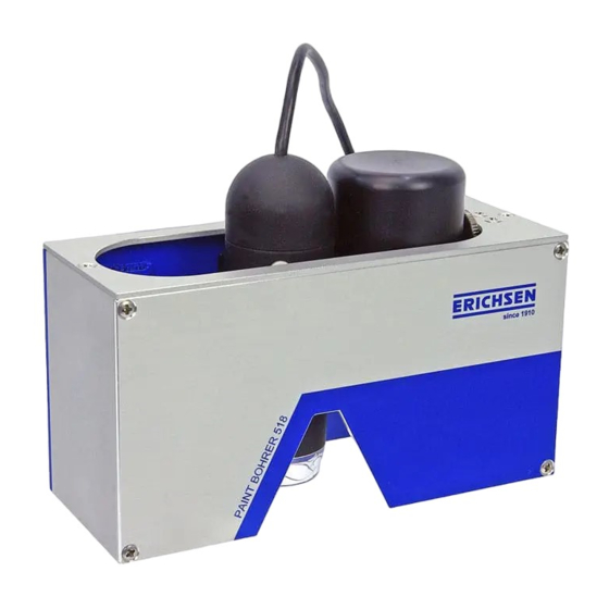
- Page 1 PAINT BORER 518 USB NOTICE Please read and precisely follow this operating manual before commissioning the instrument. Operating Manual Layer Thickness Measuring Instrument PAINT BORER Model 518 USB Country of origin: Germany Status: X/2016 BAE 518 USB...
-
Page 2: Table Of Contents
PAINT BORER 518 USB TABLE OF CONTENTS Page General information Incoming goods inspection Proper and intended usage Storage and operations Safety information Copyright protection Address of the manufacturer Device specifications Designation and type Included in the delivery 2.2.1 Base unit 2.2.2... - Page 3 PAINT BORER 518 USB Logs Special measuring problems Delamination Maintenance and care Declaration of Conformity (page 33) BAE 518 USB...
-
Page 4: General Information
1.2 Proper and intended usage The PAINT BORER 518 USB is used to measure the thickness of organic coatings on substrates using the wedge cut method. Erichsen GmbH & Co. KG is not liable for damages caused by improper use. -
Page 5: Device Specifications
PAINT BORER 518 USB 2 Device specifications 2.1 Designation and type The layer thickness measuring instrument TNO PAINT BORER Model 518 USB: (order number 2348.01.31) featuring a high-resolution digital microscope with integrated light 2.2 Included in the delivery 2.2.1 Base unit 1 No.5 drill, for layer thicknesses up to 300 microns... -
Page 6: Technical Specifications
PAINT BORER 518 USB 2.3 Technical specifications 2.3.1 Base unit Dimensions (L x W x H) 155 mm x 55 mm x 110 mm Weight excluding packaging: approx 850 g Drill speed: approx. 180 rpm Min. sample dimensions: 150 mm x 25 mm... -
Page 7: Commissioning - Operations - Handling
PAINT BORER 518 USB 3 Commissioning – Operations – Handling Knurled ring for adjusting the lighting brightness Digital microscope Drill Adjustment for the image sharpness (the sharpness is pre-set) BAE 518 USB... - Page 8 PAINT BORER 518 USB Battery compartment Power supply socket Button (additional lighting) BAE 518 USB...
-
Page 9: Commissioning / Driver And Software Installation
We have deliberately omitted an installer program to simplify file access and to minimize OS dependencies. Copy the Erichsen file (from the supplied USB flash drive) onto the C: drive or another Windows partition. Open the Erichsen folder. -
Page 10: Commissioning And Calibration
PAINT BORER 518 USB 3.2 Commissioning and calibration The calibration is only required for the initial commissioning and after the optical focusing. Start the program (main screen) Click on the Grab image button (= live image) Align the standard plate with the calibration circle in the middle. - Page 11 PAINT BORER 518 USB Click on the Grab image button again The image is now stored for calibration. Click on the Configuration button. The configuration window opens. Click on the Calibration button ; the button will now be colored red.
- Page 12 PAINT BORER 518 USB Use the mouse pointer and the left mouse button to trace the edge of the calibration circle in the main window. correct wrong wrong If the first attempt is not successful, you may retrace the circle with the left mouse button until it is correct.
- Page 13 PAINT BORER 518 USB The calibration value should be maintained between 5.0 and 6.0 microns. For the vertical measurement of the drilled hole diameter, the resolution of the USB camera is approximately 5.5 microns per pixel. (This can vary from 5 to 6 microns, depending on the focus adjustment of the lens.)
-
Page 14: Power Supply
PAINT BORER 518 USB 3.3 Power supply The PAINT BORER 518 USB can be operated in the field – when it is disconnected from the mains power supply. A 9-volt NiCd rechargeable battery (IEC No. 6F22) can be used as the internal voltage source. Alternatively, a 9-volt non-rechargeable battery (alkaline type IEC No. -
Page 15: Setting The Image Focus
PAINT BORER 518 USB Briefly press the button to turn on the LED. The mid-level brightness will be set automatically after the LED is turned on. The three levels of brightness can be switched on consecutively by repeatedly pressing the button. -
Page 16: Slider Mechanism
3.5 Wedge cut drill (Refer to the table in section 2.3.2.) The basic configuration of the PAINT BORER 518 USB includes a boring tool for the measurement range of 300 microns (the No.5 drill). Additional drills are available as accessories: for up to 200 microns (drill number 2), 500 microns (drill number 4), 1000 microns (drill number 1) and 2000 microns (drill number 3). -
Page 17: Program Functions
PAINT BORER 518 USB 4 Program functions 1. Double click on to open the program. 2. The Main screen is shown below. 4.1 Menu and screen components Quit: Exits the program. Green: Connection to the camera is established. Red: there is no connection. - Page 18 PAINT BORER 518 USB Configuration: Opens the window for calibration and for language selection. Load language: Opens the window for selecting the language. Select the desired *.lan (language) file and load it by clicking on Load. The selected language will be activated after the program is restarted.
-
Page 19: Information About The Sample
PAINT BORER 518 USB The Grab image button is now colored red. When the button is pressed again, the image is stored for processing and can be measured. "Measurement" is discussed separately on page 23 in section 5.3. Save button: the measurement is saved and the log file is created. -
Page 20: Selection Of Drill And Image Color
PAINT BORER 518 USB 4.3 Selection of drill and image color 4.3.1 Drill selection You can select one of the five standard drills (for example:drill number 5 is included in the delivery). It is very important to choose the proper drill for the measurement. -
Page 21: Composition Of The Sample (Layer Composition)
PAINT BORER 518 USB 4.4 Composition of the sample (layer composition) A measurement of the layer structure is possible for up to six layers: You can activate (with ) or deactivate the selection, depending on the layer compositions. You should only select the layers that are actually present in your sample! Substrate: The coated substrate can be specified here. - Page 22 PAINT BORER 518 USB BAE 518 USB...
-
Page 23: Layer Thickness Measurement
PAINT BORER 518 USB 5 Layer thickness measurement 5.1 Preparing the test samples First, select a flat section on the sample such that the PAINT BORER's rubber side skids can safely stand on the base. The minimum sample dimensions are 150 x 25 mm. -
Page 24: Carrying Out The Measurement (Via Software)
PAINT BORER 518 USB 5.3 Carrying out the measurement (via software) After drilling the sample, move the PAINT BORER's slide all the way to the right (so that microscope is above the drilled hole). Use the additional lighting if needed. -
Page 25: Selecting The Circles
PAINT BORER 518 USB 5.3.2 Selecting the circles (Always start with circle 1.) Circle 1 is always the inner substrate circle. Circle 2 is, in this case, the primer. Circle 3 is, in this case, the top coat. 5.3.3 Tracing the circles ... -
Page 26: Display Of Measured Values
PAINT BORER 518 USB 5.3.4 Display of measured values Circle 1 Circle 2 Circle 3 The measured layer thickness is displayed immediately. This procedure is the same when processing a multi-layer coating structure; only the number of circles (number of layers) changes. -
Page 27: Inserting A Customer Logo
The logo must be a PNG image with a max. size of 70 KB and max. dimensions of 450 x 160. The image should be copied into the folder "Erichsen/518/bin-141/" with the name Customer.png. (Make sure this is the exact name of the logo file!) If different logos are used, we recommend renaming the logos and leaving them in the same directory. - Page 28 PAINT BORER 518 USB BAE 518 USB...
- Page 29 PAINT BORER 518 USB 7 Logs The log files are created automatically when the measurement is saved (when the Save button is clicked on). A day folder and an hour folder are created automatically in the "Protocols" folder. Day folder...
- Page 30 PAINT BORER 518 USB PDF document BAE 518 USB...
- Page 31 PAINT BORER 518 USB 8 Special measuring problems 8.1 Delamination Brittle coating materials or coatings with poor adhesion to the base material often result in boreholes where the boundary between the coating and the substrate is not circular but rather irregularly bounded.
- Page 32 PAINT BORER 518 USB 9 Maintenance and care • The PAINT BORER 518 USB requires no maintenance. • When used in wet conditions outdoors, this measuring instrument should be completely and immediately dried off in order to avoid corrosion and malfunctions.
- Page 33 EC Declaration of Conformity EC Declaration of Conformity Wir/We ERICHSEN GmbH & Co. KG, Am Iserbach 14, 58675 Hemer, Germany erklären in alleiniger Verantwortung, dass das nachfolgend aufgeführte Produkt declare under our sole responsibility that the product described below Schichtdickenmessgerät PAINT BORER...
Need help?
Do you have a question about the 518 USB and is the answer not in the manual?
Questions and answers