Table of Contents
Advertisement
Advertisement
Table of Contents

Related Manuals for WAGNER TITANUS PRO-SENS


Summary of Contents for WAGNER TITANUS PRO-SENS
- Page 3 Air Sampling Smoke Detection System ® TITANUS PRO·SENS Technical Manual WAGNER Group GmbH Schleswigstraße 1 - 5 D-30853 Langenhagen item number: 69-30-0226 Telephone +49 (0) 511 / 97383-0 dated: 04/09 Telefax +49 (0) 511 / 97383-140 supersedes: 06/06 E-Mail s upport@wagner.de Internet www.wagner.de...
- Page 5 ® Contents TITANUS PRO·SENS Contents General 0 – 1 Introduction Safety Information Guarantee Copyright Packaging Disposal Product Description 1 – 1 ® Features of the TITANUS PRO·SENS air sampling smoke detection system Areas of Application Technical Description 2 – 1 System Description 2.1.1 Function...
-
Page 6: Table Of Contents
® TITANUS PRO · SENS Inhalt Contents Technical Data 3 – 1 ® TITANUS PRO·SENS ® Pipe system – TITANUS PRO·SENS Design 4 – 1 General 4.1.1 Regulations 4.1.2 Pipe system 4.1.3 Air flow monitoring 4.1.4 Sensitivity 4.1.5 Project planning limits Project planning 4.2.1 Project planning guidelines... - Page 7 ® Contents TITANUS PRO·SENS Contents 5.3.1.6 LOGIC·SENS 5.3.1.7 Function of the collective fault contact 5.3.1.8 Setting of the Ventilator Voltage 5.3.1.9 Connecting the ventilator ® 5.3.1.10 Setting of ventilator voltage at TITANUS PRO·SENS ® 5.3.1.11 Connecting the ventilator i TITANUS PRO ·SENS Installation of the reset board Mounting Location ®...
- Page 8 ® TITANUS PRO · SENS Inhalt Contents Filter 6.5.1 Installation of the air Filter type LF-AD-x 6.5.2 Mounting of the special filter type SF-400/650 Air return Noise suppressor 6.8. 3-Way ball valve Steam trap 6.10 Detonation prevention device 6.11 Test adapter Commissioning 7 –...
- Page 9 ® Contents TITANUS PRO·SENS Appendix Air Pressure Adjustment Tables Projection Tables System Product List Certificate of Approval of Components and Systems EMC Declaration of Conformity Inspection Protocol Glossary Conformity certification pursuant to EU Data: 04/09 PS-Inhalt-a_en_e...
- Page 10 ® TITANUS PRO · SENS Inhalt PS-Inhalt-a_en_e Data: 04/09...
- Page 11 For damage and faults resulting from the non-observance of this manual WAGNER Group GmbH, called WAGNER in the following, does not as- sume liability. This manual refers to the air sampling smoke detection systems ®...
- Page 12 • force majeure 0.4 Copyright The copyright in this Technical Manual remains with WAGNER. The manual is designed exclusively for the assembler and his col- leagues. Reproduction of the manual, including extracts, is not allowed. Copying or distribution of the manual in any form is only allowed with permission in writing from WAGNER.
- Page 13 ® TITANUS PRO·SENS General 0.5 Packaging The individual air sampling smoke detection systems are packed in ac- cordance with the anticipated transport conditions. Exclusively environ- mentally friendly materials were used for the packaging. The packaging is intended to protect the air sampling smoke detection system from being damaged until it is installed.
- Page 14 ® General TITANUS PRO·SENS 0 – 4 Date: 04/09 PS-00-a_en_e...
- Page 15 Depending on the required pipe design the air sampling points have de- fined hole diameters. For these exact airs sampling points WAGNER has developed patented aspiration-reducing film sheets with marking tape and clips that permit an easy mounting and avoid secondary noise. An- other advantage is the quick and easy retrieval and check of the air sam- pling point diameters.
- Page 16 ® Product Description TITANUS PRO·SENS Diagnostics software The diagnostic software permits a quick and reliable fault localization for maintenance and service. The current and memorized device state can be read out to a PC via a special cable. Choice of ventilator voltage The fan voltage can be set according to project planning by re-plugging the plug-in jumpers.
- Page 17 ® TITANUS PRO·SENS Product Description 1.2 Areas of Application ® The air sampling smoke detection system TITANUS PRO·SENS is a smoke detection system used for the early smoke detection and very early smoke detection in rooms and equipments. Principle Air samples are drawn from the monitoring area via a pipe system with defined air sampling points and passed to the detector module.
- Page 18 ® Product Description TITANUS PRO·SENS Room monitoring with air conditioning Room monitoring takes place in rooms with air conditioning for server rooms, etc., in ventilation ducts, via floor voids, ceiling voids, in EDP rooms, distribution cabinets, transformer cells, at climatic cabinets (see Fig. 1.2) or at climatic ducts in the by-pass.
- Page 19 ® TITANUS PRO·SENS Product Description Equipment Protection non-ventilated and ventilated installations/cabinets like f. e. distribution cabinets, switch cabinets telephone switch boards measuring and control units Fig. 1.3: Scheme - equipment monitoring with the air sampling smoke detection system ® TITANUS PRO·SENS ®...
- Page 20 ® Product Description TITANUS PRO·SENS 1 – 6 Date: 04/09 PS-01-a_en_e...
- Page 21 ® TITANUS PRO·SENS Technical Description 2 Technical Description 2.1 System Description ® The air sampling smoke detection system TITANUS PRO·SENS con- sists of the basic device and the pipe system. The most important components of the basic device are the range of op- tical detector modules to detect the smoke aerosols, the aspiration unit to pass the air samples to the detector module and the air flow sensor in or- der to monitor the pipe system for fracture and blockage.
- Page 22 ® Technical Description TITANUS PRO · SENS 2.1.1 Function The aspiration unit in the basic device draws air samples from the area to be monitored via a pipe system with defined air sampling points. The air samples are then passed to the sensitive detector module (refer to Fig.. Detector module Dependent on the response sensitivity of the used detector module (up to ®...
- Page 23 ® TITANUS PRO·SENS Technical Description After a delay period which can be programmed by switches the fault is indicated at the air sampling smoke detection system and, if required, the fault signal is passed to the central fire detection unit (CFDU) via a fault contact.
- Page 24 ® Technical Description TITANUS PRO · SENS ® Relay output TITANUS PRO·SENS possesses a potential-free change-over contact for the existing alarm threshold and the collective fault . Thus, the air sampling smoke detection system can be connected to collective and addressable detection lines of any central fire detection unit (CFDU).
- Page 25 ® TITANUS PRO·SENS Technical Description ® 2.2 TITANUS PRO·SENS and accessories 2.2.1 Overview Connect ions reset board (option) central fire panel/ power supply pipe system air return air sampling smoke detection system ® type TITANUS PRO · SENS to the next air sampling smoke detection system device support installation kit line module...
- Page 26 ® Technical Description TITANUS PRO · SENS ® 2.2.2 Basic device TITANUS PRO·SENS ® The basic device TITANUS PRO·SENS consists of the following com- ponents: • plastic housing • plastic connection piece • integrate pipe return • Connection for pipe with 25 mm outside diameter •...
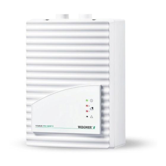
- Page 27 ® TITANUS PRO·SENS Technical Description ® Numbers Function Explanation TITANUS PRO·SENS Fig. displays (refer to Fig. 2.5) ON (green LED) operation display alarm (red LED) alarm display fault (yellow LED) fault pipe system or failure ventilator or fault detector module connection for air return pipe to return the air cable entry of fire detection cable for con-...
- Page 28 ® Technical Description TITANUS PRO · SENS 2.2.3 Diagnostics DIAG-connector Diagnostictool TITANUS PRO·SENS ® Fig. 2.6: Diagnostic software for reading out the device state For maintenance and service the diagnostic software is able to display the memorized and current device state as well as fault signals of ®...
- Page 29 ® TITANUS PRO·SENS Technical Description 2.2.4 Response Indicators For a hidden installation of the air sampling smoke detection system it is necessary to mount an alarm display in a clearly visible place. ® TITANUS PRO · SENS offers the possibility to connect the response in- dicators DJ1191 and DJ1192.
- Page 30 ® Technical Description TITANUS PRO · SENS 2.2.5 Device Support rack support type Unirack ® Fig. 2.8: Support for the air sampling smoke detection system TITANUS PRO·SENS ® TITANUS PRO·SENS can be directly mounted to a wall. If required, additional supports are available e.g. for the fixing at racks. 2 –...
- Page 31 ® TITANUS PRO·SENS Technical Description 2.3 Pipe system 2.3.1 Overview of available pipe components C onnec t ions P ipe system detonation preventation arc 90 ° device steam trap sleeve sampling hose ceiling lead through special filter air filter double screw joint T-piece air sampling point testadapter...
- Page 32 ® Technical Description TITANUS PRO·SENS Blow-through system In areas where dust particles or icy conditions are possible it might be necessary to blow through the air sampling pipe system and aspiration points. Figs. 2.10 and 2.11 show the components of a manual and auto- matic blow-through system.
- Page 33 ® TITANUS PRO·SENS Technical Description 2.3.2 Air sampling points for room monitoring 2.3.2.1 Aspiration-reducing film sheets Fig. 2.12: Air sampling point with aspiration-reducing film sheet and marking tape An air sampling point is a 10 mm-hole in the air sampling pipe. This hole is sealed by means of a patented aspiration-reducing film sheet which has an opening of the required diameter.
- Page 34 ® Technical Description TITANUS PRO·SENS 2.3.2.2 Air flow reducer clips air flow reducer for deep freeze storage plastic clip for air flow reducer Fig. 2.13: Air flow reducer for dirty areas and deep freeze storage The air sampling points, when used in areas where blockages can occur, are equipped with a patented plastic clip, type AK-C, and a patented flexi- ble air flow reducer, type AK-x (refer to Fig 2.14).
- Page 35 35 mm. The aspiration-reducing film sheets are available in two colours (pure white, RAL 9010 and papyrus white, RAL 9018) and come in special colours if required. calculation is made by WAGNER 2 – 15 PS-02-a_en-b_e...
- Page 36 ® Technical Description TITANUS PRO·SENS 2.3.4 Air filter for dusty areas air filter for ADx and TITANUS ® air sampling pipe type LF-AD special filter for ADx and TITANUS ® type SF-650 type SF-400 ® Fig. 2.15: TITANUS PRO·SENS with air filter In highly dusty areas air filters are to be used in order to protect the de- tector module of the device.
- Page 37 ® TITANUS PRO·SENS Technical Description 2.3.5 Air return for pressurised and dusty areas ® Fig.2.16: Principle of air return with TITANUS PRO·SENS ® If the air sampling smoke detection system TITANUS PRO · SENS the pipe system are installed in two areas P1 and P2 with different air pressures, the air is to be returned to the pressure area of the pipe sys- tem (refer to Fig.
- Page 38 ® Technical Description TITANUS PRO·SENS 2.3.6 Noise suppressor noise suppressor ® TITANUS PRO·SENS ® Fig. 2.18: TITANUS PRO·SENS with noise suppressor By using the SD-1 noise suppressor, the noise level can be reduced by up to 10 db(A) for use in areas in which low noise emissions are required ®...
- Page 39 ® TITANUS PRO·SENS Technical Description 2.3.7 Steam trap for humid areas elbow 45° steam trap (max. 16 bar option) elbow 45° ® TITANUS PRO · SENS Fig. 2.19: Steam trap to eliminate water vapour from the pipe system and to collect the con- densate from the pipe system ®...
- Page 40 ® Technical Description TITANUS PRO·SENS 2.3.8 Detonation prevention device for endangered areas Fig. 2.20: Detonation prevention device in the air sampling smoke detection system and air return system ® TITANUS PRO·SENS can also be used in dangerously explosive areas by installing a detonation prevention device. Both must be installed out- side the protected area.
- Page 41 ® TITANUS PRO·SENS Technical Description Protection Type Approval Nominal Gap Width Explosion Groups EG IIA > 0,7 mm BAM* EG IIB3 > 0,5 mm IIB1 – IIB3 BAM* EG IIC > 0,2 mm BAM* Bundesanstalt für Materialprüfung (Federal German Office of Material Research) The connection between the air sampling smoke detection system and the detonation prevention device is a metal pipe.
- Page 42 ® Technical Description TITANUS PRO·SENS 2 – 22 Date: 04/09 PS-02-a_en-b_e...
-
Page 43: Technical Data
® TITANUS PRO·SENS Technical Data 3 Technical Data All listed power values relate to a surround temperature of 20ºC. INSTRUCTION ® 3.1 TITANUS PRO·SENS TITANUS TITANUS ® ® PRO·SENS PRO·SENS supply voltage (Ue) 14 to 30 V DC Voltage nominal supply voltage 24 V DC = 6,9 V = 9 V... - Page 44 ® Technical Data TITANUS PRO·SENS TITANUS TITANUS ® ® PRO·SENS PRO·SENS ® TITANUS PRO · SENS -20° to +60°C Temperature Range deep freeze variety -40° to +60°C non-condensed 10 to 95 % rf Humidity construction type radial Ventilator service life of the ventilator (12 V) 43.500 h at 24°C alarm red alarm display...
- Page 45 ® TITANUS PRO·SENS Technical Data TITANUS TITANUS ® ® PRO·SENS PRO·SENS 2-SL Voltage supply voltage (Ue) 14 to 30 V DC nominal supply voltage 24 V DC Voltage with Strom ventilator control board FC-2 6,5 V 6,9 V 6,5 V 6,9 V starting current (at 24V) 300 mA...
- Page 46 ® Technical Data TITANUS PRO·SENS TITANUS TITANUS ® ® PRO·SENS PRO·SENS 2-SL protection class (DIN IEC 34 part 5) IP 20 Protection classification material plastic (ABS) Housing colour housing papyrus white, RAL 9018 0° to +40°C Temperature range not condensed 10 to 95 % rf Humidity type...
-
Page 47: Titanus Pro·sens
® TITANUS PRO·SENS Technical Data 3.2 Pipe system – ® TITANUS PRO·SENS Pipe system TITANUS TITANUS ® ® PRO·SENS PRO·SENS ® ® PRO·SENS PRO·SENS 2-SL max. pipe length 300 m 560 m Pipe system max. number of air sampling points max. - Page 48 ® Technical Data TITANUS PRO·SENS 3 – 6 Data: 04/09 PS-03-a_en_e...
-
Page 49: Design
® TITANUS PRO·SENS /Rev.a Pipe Design 4 Design 4.1 General The following describes the project planning of the air sampling smoke detection system to EN 54-20. The basic conditions are described in Chapter 4.1. The project planning is to be conducted in accordance with Chapter 4.2. -
Page 50: Regulations
® Pipe Design TITANUS PRO·SENS /Rev.a 4.1.1 Regulations The current respective national regulations in each particular country must also be complied with and project planning must be adjusted to such regulations. EN 54-20 The air sampling smoke detection systems shall be planned in accordance with the project planning guidelines described in Chapter 4.2.1 in order to be compliant with EN 54-20. -
Page 51: Pipe System
® TITANUS PRO·SENS /Rev.a Pipe Design 4.1.2 Pipe system When planning the pipe system, it must be ensured that reliable fire detection is guaranteed for any fire present in an installation or in a monitored area. Fig. 4.1 depicts an example of a U-pipe system with symmetrical or asymmetrical design and the diameters of the aspiration apertures calculated according to Chapter 4.6.2 “Standard planning.”... - Page 52 ® Pipe Design TITANUS PRO·SENS /Rev.a Longer pipe intake lines Pipes with a diameter of 32mm or 40mm may be used for long pipe intake lines in accordance with the chapter "Special project planning". This reduces the air resistance of the pipe intake line or makes it possible to achieve a greater equilibrium for sampling via outgoing transmission lines.
- Page 53 ® TITANUS PRO·SENS /Rev.a Pipe Design ® I-pipe system ® U-pipe system ® TITANUS M-pipe system ® Double U-pipe system ® Quadruple U-pipe system Fig. 4.2: Pipe designs 4 – 5 PS-04-a_en_e Date : 04/09...
- Page 54 INSTRUCTION Special cases If the pipe system does not match the project planning guidelines described here due to structural constraints, WAGNER should make the individual calculations for such a case. Checking Check detection reliability with activation tests in cases where use of the system is critical.
-
Page 55: Air Flow Monitoring
® TITANUS PRO·SENS /Rev.a Pipe Design 4.1.3 Air flow monitoring EN 54-20 requires the recognition of a 20 percent change in the air flow volume by the detector module’s air flow sensor system. In order to accomplish this, the air flow sensor system’s triggering threshold must be set to level II. - Page 56 ® Pipe Design TITANUS PRO·SENS /Rev.a Level I limitations The air flow monitoring may only be set to level I if: Project planning according to “Individual aperture monitoring” has been carried out (see Chap. 4.3.1 “Pipe project planning individual aperture monitoring”), the air flow sensor has been compensated depending on the air pressure (see Chap.
-
Page 57: Sensitivity
® TITANUS PRO·SENS /Rev.a Pipe Design 4.1.4 Sensitivity According to EN 54-20, the sensitivity of a air sampling smoke detection system can be divided into particular fire sensitivity classes. These sensitivity classes describe particular example applications in which the systems can be used. Permissible system project planning can be determined for each classification according to Chapter 4.2. -
Page 58: Project Planning Limits
® Pipe Design TITANUS PRO·SENS /Rev.a 4.1.5 Project planning limits The following limit values must be complied with at all times with the ® TITANUS PRO·SENS per pipe system connected. The minimum pipe length between 2 aspiration apertures is 4 m. The maximum pipe length between 2 aspiration apertures is 12 m. -
Page 59: Project Planning
Components which have not been approved by WAGNER are used, CE conformity on the basis of EN 54-20 will not be possible. INSTRUCTION... -
Page 60: Pipe Accessories
® Pipe Design TITANUS PRO·SENS /Rev.a 4.2.2 Pipe accessories Air filters Type Application Examples LF-AD Coarse filter for separating Dust, insects, fibres, hair, particles > approx. 15 µm cinders, pollen LF-AD-1 Filter for separating particles As above. Additionally: > approx. 10 µm Colour pigments and fine dust LF-AD-2... -
Page 61: Sensitivity And Pipeline Project Planning
® TITANUS PRO·SENS /Rev.a Pipe Design 4.2.3 Sensitivity and pipeline project planning 4.2.3.1 Pipeline project planning with pipe accessories The following project planning tables for pipeline project planning can be found in the appendix for each previously selected pipe accessory. Project planning without filter Project planning with LF-AD air filter Project planning with LF-AD-1 air filter... - Page 62 ® Pipe Design TITANUS PRO·SENS /Rev.a Procedure In the following example, a project plan is supposed to fulfil class B requirements without air filters, with 8 apertures and with the additional use of a condensation separator. The red arrows show the possible project plans with varying pipe shapes and fan voltages.
- Page 63 ® TITANUS PRO·SENS /Rev.a Pipe Design 4 – 15 PS-04-a_en_e Date : 04/09...
- Page 64 ® Pipe Design TITANUS PRO·SENS /Rev.a Results: The following modules may optionally be used with the corresponding settings for class B or A: Module 0.015 % LT/m – with a sensitivity of min. 0.12 % LT/m Module 0.1 % LT/m – with a sensitivity of min. 0.2 % LT/m Possible system parameters: I-pipe system ≥...
-
Page 65: Aperture Diameter
® TITANUS PRO·SENS /Rev.a Pipe Design 4.2.4 Aperture diameter The aperture diameters of the aspiration apertures can be found in the corresponding table for the respective pipe configuration: I- pipe Fig. 4.4: I-pipe system Number of Aspiration apertures apertures Sampling aperture ∅... - Page 66 ® Pipe Design TITANUS PRO·SENS /Rev.a U-pipe ® TITANUS Fig. 4.5: U-pipe system Aspiration apertures Number of apertures Sampling aperture ∅ in mm — — — — — — — — — — — — — — — — — —...
- Page 67 ® TITANUS PRO·SENS /Rev.a Pipe Design Double U-pipe ® Double -U-pipe syste m Fig. 4.7: Double U-pipe system Aspiration apertures Number of apertures Sampling aperture ∅ in — — — — — — — — — — — — — —...
-
Page 68: Special Project Planning
® Pipe Design TITANUS PRO·SENS /Rev.a 4.3 Special project planning 4.3.1 Project planning for individual aperture monitoring The following system parameters apply to the detection of an individual or a particular number of blocked aspiration apertures, depending on pipe configuration. The specifications according to Chapter 4.2 apply to project planning. - Page 69 ® TITANUS PRO·SENS /Rev.a Pipe Design Number of Aspiration apertures apertures Sampling aperture ∅ in mm — — — — — — — — — — — — — — — — — — — — — — — — —...
-
Page 70: U-Shape Pipe System
® Pipe Design TITANUS PRO·SENS /Rev.a 4.3.1.2 U-shape pipe system 1 pipe system ® TITANUS PRO · SENS 2 pipe systems ® TITANUS PRO · SENS Fig. 4.10: U-shape pipe system for area protection ® Min. distance from TITANUS to T-piece Limit values ®... - Page 71 ® TITANUS PRO·SENS /Rev.a Pipe Design Number of Aspiration apertures apertures per pipe system Sampling aperture ∅ in mm — — — — — — — — — — — — — — — — — — — — — U-pipe system triggering thresholds Number of apertures per pipe system...
-
Page 72: M-Pipe System
® Pipe Design TITANUS PRO·SENS /Rev.a 4.3.1.3 M-pipe system 1 pipe system ® TITANUS ® TITANUS PRO·SENS 2 pipe systems ® TITANUS PRO·SENS ® TITANUS Fig. 4.11: M-shape pipe system for area protection ® Min. distance from TITANUS to T-piece Limit values ®... - Page 73 ® TITANUS PRO·SENS /Rev.a Pipe Design Number of apertures Aspiration apertures per pipe system Sampling aperture ∅ in — — — — — — M-pipe system triggering thresholds Number of apertures per pipe system 1 blocked aperture — — 2 blocked apertures —...
-
Page 74: Double U-Pipe System
® Pipe Design TITANUS PRO·SENS /Rev.a 4.3.1.4 Double U-pipe system 1 pipe system ® TITANUS PRO·SENS 2 pipe systems ® TITANUS PRO·SENS Fig. 4.12: Double U pipe system for area protection Min. distance from Limit values ® TITANUS to last T-piece Max. - Page 75 ® TITANUS PRO·SENS /Rev.a Pipe Design Number of aspiration apertures per Aspiration apertures pipe system Sampling aperture ∅ in mm — — — Double U-pipe system triggering thresholds Number of apertures per pipe system 1 blocked aperture — — 2 blocked apertures —...
-
Page 76: Simplified Pipe Project Planning
® Pipe Design TITANUS PRO·SENS /Rev.a 4.3.2 Simplified pipe project planning Simplified project planning is used for equipment protection and in rooms with small dimensions. The advantage in this project planning is the uniform diameters of the aspiration apertures. The specifications according to Chapter 4.2 apply to project planning. The following limit values and aperture diameters should also be taken into account. -
Page 77: U-Pipe System
® TITANUS PRO·SENS /Rev.a Pipe Design 4.3.2.2 U-pipe system 1 pipe system ® TITANUS PRO ·SENS ® TITANUS 2 pipe systems ® TITANUS PRO ·SENS ® TITANUS Fig. 4.14: U-pipe system, e.g. for equipment protection ® Min. distance from TITANUS to T-piece Limit values ®... -
Page 78: M-Pipe System
® Pipe Design TITANUS PRO·SENS /Rev.a 4.3.2.3 M-pipe system 1 pipe system ® TITANUS ® TITANUS PRO ·SENS 2 pipe systems ® TITANUS PRO ·SENS ® TITANUS Fig. 4.15: M-pipe system for area protection ® Limit values Min. distance from TITANUS to last T-piece ®... -
Page 79: Double U-Pipe System
® TITANUS PRO·SENS /Rev.a Pipe Design 4.3.2.4 Double U-pipe system 1 pipe system ® TITANUS PRO ·SENS ® TITANUS 2 pipe systems ® TITANUS ® TITANUS PRO ·SENS Fig. 4.16: Double U-pipe system, e.g. for equipment protection Limit values Min. distance from ®... -
Page 80: Project Planning With Long Intake Lines
® Pipe Design TITANUS PRO·SENS /Rev.a 4.3.3 Project planning with long intake lines Project planning for long pipe intake lines may only be carried out under use of pipes with a diameter of 32mm or 40mm. Observe national regulations during project planning! INSTRUCTION The pipe intake line here refers to the pipe system between the air sampling smoke detection system and the last T-piece (U- and double U-... -
Page 81: Project Planning With Acceleration Apertures
Exclusively tools approved by WAGNER are to be used for transport time calculations. The acceleration apertures can also cause a reduction in the sensitivity of the sampling aperture due to additional air supply. - Page 82 ® Pipe Design TITANUS PRO·SENS /Rev.a Aspiration apertures Pipe shape 0.33 0.50 0.60 0.66 0.71 0.75 0.77 0.80 0.81 0.83 0.84 0.85 0.86 0.33 0.50 0.60 0.66 0.71 0.75 0.77 0.80 0.81 0.83 0.33 0.50 0.60 0.66 0.71 0.75 0.77 Double U 0.33 0.50...
- Page 83 ® TITANUS PRO·SENS /Rev.a Pipe Design Example: A double U-pipe system with 24 aspiration apertures is planned in order to meet requirements for class B. According to EN 54-20, 24 apertures at a sensitivity of 0.1 % LT/m are approved to meet requirements for class B.
-
Page 84: Project Planning For Forced Air Flow
® Pipe Design TITANUS PRO·SENS /Rev.a 4.3.5 Project planning for forced air flow Air conditioning duct monitoring Air conditioners are distinguished between low-speed and high-speed systems (see table below). The specifications provided in this chapter apply only to low-speed systems. There are not enough empirical values available for high-speed systems. - Page 85 ® TITANUS PRO·SENS /Rev.a Pipe Design If it is absolutely necessary to attach the pipe system directly behind baffles, sound suppressers or angles, the main flow speed areas will have to be monitored (see Fig. 4.19/20). Fig. 4.20: Change in direction of a duct without baffles sound absorption hole air conditioning duct...
- Page 86 ® Pipe Design TITANUS PRO·SENS /Rev.a Fig. 4.22: Air recirculation Air recirculation The air recirculation must take place at a distance of at least 2 m from the sampling. The open end of the air recirculation should be bevelled at a 45°...
- Page 87 ® TITANUS PRO·SENS /Rev.a Pipe Design The distances of the aspiration apertures to each other and to the wall of the duct are represented in the following table. Duct cross section Duct cross section Bore distance ≤ 0.5 m² > 0.5 m² Distance from aspiration 100 to 200 mm 200 to 300 mm...
-
Page 88: Mains Supply
® Pipe Design TITANUS PRO·SENS /Rev.a 4.4 Mains supply The alarm-ready status in the fire protection system and the aperture of an alarm are taken into account when rating the external mains supply. In the system's alarm-ready status, the mains supply must supply standby current to the air sampling smoke detection systems and ensure that the emergency power batteries are charging in accordance with DIN VDE 0833 Part 1. - Page 89 ® TITANUS PRO·SENS /Rev.a Pipe Design Line calculation The maximum line length results from the permissible drop in voltage on the input line. The permissible drop in voltage is the difference of the final discharging voltage of the emergency power battery (21.5 V) and the lowermost operating voltage limit of the air sampling smoke detection systems.
- Page 90 ® Pipe Design TITANUS PRO·SENS /Rev.a 4 – 42 Date: 04/09 PS-04-a_en_e...
-
Page 91: Installation Titanus Pro·sens
® TITANUS PRO·SENS Installation 5 Installation ® TITANUS PRO·SENS 5.1 General The regulations, guidelines and instructions given in chapter 4.1 apply. The following is to be considered when mounting the air sampling smoke ® detection system TITANUS PRO·SENS Any changes in the design of installations are to be avoided. If chan- ges are inevitable the operator, manufacturer and/or supplier are to be informed (written approval). -
Page 92: Opening The Titanus Pro·sens
® Installation TITANUS PRO·SENS ® 5.2 Opening the TITANUS PRO·SENS display board (rear) base board ® Fig. 5.1: Opening the TITANUS PRO·SENS air sampling system The components on the base and circuit board must be protected from damage with an anti-static set. ATTENTION ®... -
Page 93: Settings
® TITANUS PRO·SENS Installation 5.3 Settings 5.3.1 Detector module detector module ® Fig. 5.2: Standard settings on the detector module of TITANUS PRO·SENS 5.3.1.1 Setting of the response sensitivity The sensitivity of the detector module is set via the switch S1 (1, 2) on the detector module (refer to Fehler! Verweisquelle konnte nicht ge- ®... -
Page 94: Delay Period Of The Alarm Activation
® Installation TITANUS PRO·SENS 5.3.1.2 Delay period of the alarm activation The delay period for the alarm thresholds can be set via the switch S1 (3, 4). As a standard the delay period for the alarm is set to 10 sec. If the smoke level increases during operation so that the alarm threshold is reached the delay period starts. -
Page 95: Delay Period Of The Air Flow Fault
® TITANUS PRO·SENS Installation 5.3.1.4 Delay period of the air flow fault Set the delay period for the transmission of a fault signal via the switch S1 (7, 8) on the detector module (refer to Fehler! Verweisquelle ® konnte nicht gefunden werden.) of TITANUS PRO·SENS Setting of the Delay Period Switch S1 Switch S1... -
Page 96: Function Of The Collective Fault Contact
® Installation TITANUS PRO·SENS 5.3.1.7 Function of the collective fault contact Fig. 5.3: Jumper settings on the collective fault contact The contact type (break contact or make contact) of the collective fault is set using the jumper JU2 and JU3. Adjust with jumper JU2 the contact type of the 1. -
Page 97: Setting Of The Ventilator Voltage
® TITANUS PRO·SENS Installation 5.3.1.8 Setting of the Ventilator Voltage Fig. 5.4: Switching of the ventilator voltage on the base board The standard setting of the ventilator voltage is 6.9 V. In critical areas the ventilator voltage can be switched from 6.9 V to 9 V by removing the jumper JU1 in order to increase the transport speed in the pipe system and thus to guarantee a quicker detection in case of greater pipe lengths. -
Page 98: Connecting The Ventilator
® Installation TITANUS PRO·SENS 5.3.1.9 Connecting the ventilator The electrical connection of the ventilator is made via terminal block X5 ® (FAN) on the base board of TITANUS PRO·SENS connect the red connecting lead of the ventilator with terminal block X5 / clip 1 (+) connect the black connecting lead of the ventilator with terminal block X7 / clip 2 (-) -
Page 99: Setting Of Ventilator Voltage At Titanus Pro·sens
® TITANUS PRO·SENS Installation ® 5.3.1.10 Setting of ventilator voltage at TITANUS PRO·SENS BR1 BR2 Fig. 5.5: Switching the fan voltage and fan connection terminal board on the FC-2 or FC-3 fan control circuit board The default setting for the fan voltage is 6.9 V. The fan voltage can be adjusted according to project planning by plugging or removing the BR 1 and/or BR 2 bridges. - Page 100 ® Installation TITANUS PRO·SENS The JU 1 bridge on the base board must always be removed. ATTENTION Conduct the air flow initialisation again if you change the fan voltage. Only close or open the BR 1 and BR 2 bridges when the device is turned off.
-
Page 101: Connecting The Ventilator I Titanus Pro ·Sens
® TITANUS PRO·SENS Installation ® 5.3.1.11 Connecting the ventilator i TITANUS PRO ·SENS The electrical connection of the fan control circuit board is made via ter- minal block X5 (FAN) on the base board (see fig. 5.3) of TITANUS ® TOP·SENS The electrical connection of the ventilator is made via terminal block X1 (FAN) on the fan control circuit board (see fig. -
Page 102: Installation Of The Reset Board
® Installation TITANUS PRO·SENS 5.4 Installation of the reset board ® The reset board can be installed into TITANUS PRO·SENS as an op- ® tion. If several TITANUS PRO·SENS are connected to one detection line ® the reset board is only installed to the last TITANUS PRO·SENS on the detection line. - Page 103 ® TITANUS PRO·SENS Installation reset board type E548 ® Fig. 5.6: Installation of the reset board in TITANUS PRO·SENS ® ® Installation in TITANUS In order to install the reset board in TITANUS PRO · SENS the following steps are to be followed: Carefully unlock the snap-in closures of the housing using a screwdriver by simultaneously pressing in both clips located at one side of the housing lid.
-
Page 104: Mounting Location
® Installation TITANUS PRO·SENS 5.5 Mounting Location 5.5.1 Fixing of the air sampling system ® TITANUS PRO·SENS Mount the air sampling system in such a way that the displays are clearly visible. Screw the air sampling smoke detection system either directly to the wall with its bottom casing or mount it by means of a special support (refer to 2.2.5 "Device Support"). - Page 105 ® TITANUS PRO·SENS Installation Distances of the holes The distances of the holes are given in the following figures (all dimen- sions in mm). ® Fig. 5.8: TITANUS hole-spacing without support ∅ Fig. 5.9: Hole distances of the support type MT-1 5 –...
-
Page 106: Connection Of The Air Sampling Pipe
® Installation TITANUS PRO·SENS 5.5.2 Connection of the air sampling pipe air sampling pipe Fig. 5.10: Connection of the air sampling pipe to the air sampling smoke detection system ® TITANUS PRO·SENS Connection of In order to connect the air sampling pipe to TITANUS ®... -
Page 107: Electrical Connection
® TITANUS PRO·SENS Installation 5.6 Electrical connection In order to prepare the electrical connections follow the steps below: 1. Break through the required cable entries e.g. by means of a screw- driver. 2. Attach the plastic connection pieces M 20 or M 25 to the cable entries. 3. -
Page 108: Connection To Central Fire Panel, With Reset Button
® Installation TITANUS PRO·SENS 5.6.1 Connection to central fire panel, with reset button The relay contacts on the base board can be used to e.g. connect ® TITANUS PRO·SENS to a central fire panel, to trigger signalling de- vices, security management systems etc. It is also possible to connect a response indicator. -
Page 109: Connection Of Several Titanus Pro·sens
® TITANUS PRO·SENS Installation ® 5.6.2 Connection of several TITANUS PRO·SENS without central fire panel, with reset button fault contact * detector module 1 external response indicator detector module 2 alarm relais detector module 2 fault contact * detector module 2 24 V reset external response indicator... -
Page 110: Connection To Central Fire Panel, With Reset Board
® Installation TITANUS PRO·SENS 5.6.3 Connection to central fire panel, with reset board fault contact * detector module 1 external response indicator detector module 2 alarm relais detector module 2 fault contact * detector module 2 + Ub - Ub + Reset - Reset 24 V... -
Page 111: Application Of Titanus Pro·sens
® TITANUS PRO·SENS Installation ® 5.7 Application of TITANUS PRO·SENS ® the smoke detection system AlgoRex In general, there are different possibilities to connect the potential-free alarm and fault contacts of the air sampling smoke detection system ® ® TITANUS PRO · SENS to the smoke detection system AlgoRex •... -
Page 112: Potential-Free Connection Diagram
® Installation TITANUS PRO·SENS 5.7.1.1 Potential-free connection diagram fault contact * detector module 1 external response indicator detector module 2 5,6V alarm relais detector module 2 fault contact * detector module 2 24 V reset external response indicator detector module 1 5,6V alarm relais detector module 1... -
Page 113: Application Of Titanus Pro·sens
® TITANUS PRO·SENS Installation ® 5.7.2 Application of TITANUS PRO·SENS with ® AlgoRex line modules ® The corresponding line modules (AnalogPLUS or interactive) allow to ® ® connect TITANUS PRO·SENS to the AlgoRex smoke detection sys- tem. The required line modules are directly installed in the housing of ®... - Page 114 ® Installation TITANUS PRO·SENS Fix the line module to the mounting plate by means of the mount- ing material provided with the mounting kit. Install the mounting plate equipped with the line module in one of ® the four possible positions in the housing of TITANUS PRO·SENS Wire the line module according to the connection diagram on the next page.
-
Page 115: And Analogplus-Technology
® TITANUS PRO·SENS Installation ® 5.7.2.2 TITANUS PRO·SENS and AnalogPLUS-technology input module (fault) Jumper of DC1131-31 AnalogPLUS ® 4k75 fault contact * input module 4k75 detector module 1 (Fire alarm) of DC1131-31 external response indicator AnalogPLUS ® Jumper detector module 2 alarm relais detector module 2 input module... -
Page 116: And Interactive Technology
® Installation TITANUS PRO·SENS ® 5.7.2.3 TITANUS PRO·SENS and interactive technology L1 M1 L2 L3 M3 Detection line monitors an underbreaking 4k75 fault contact * Input module DC1157-AA interactive detector module 1 external response indicator detektor module 2 4k75 alarm relais detector module 2 fault contact * 4k75... -
Page 117: Application Titanus Pro·sens
® TITANUS PRO·SENS Installation ® 5.8 Application TITANUS PRO·SENS SigmaSys-technology ® The use of the Siemens SigmaSys-technology in TITANUS PRO·SENS requires the installation of the contact coupler SPF 5300 into the air sam- pling smoke detection system. The installation of this coupler is necessary in order to integrate alarm and fault messages with their address into the detection loop. -
Page 118: Mounting Of The Contact Coupler Spf 5300 For The Extension
® Installation TITANUS PRO·SENS 5.8.1 Mounting of the contact coupler SPF 5300 for the extension Fig. 5.19: Mounting of the contact coupler SPF 5300 Mounting in ® TITANUS PRO·SENS In order to install the contact coupler SPF 5300 into the air sampling ®... -
Page 119: Electrical Connection
® TITANUS PRO·SENS Installation 5.8.2 Electrical connection The connection is made via the terminal blocks X6/ X7 on the base board ® of TITANUS PRO·SENS and via the terminal block of the contact cou- pler SPF 5300. Note the permissible cable cross sections of the corre- sponding screw joints and the permissible wire cross sections of the ter- minals (refer to chapter 3 "Technical Data"). -
Page 120: Installation Of The Second Detector Module
® Installation TITANUS PRO·SENS 5.9 Installation of the second detector module Fig. 5.21: Installation of the second detector module Only carry out the following work if the device is current-free. With a slot screwdriver, carefully undo the snap-in closures of the housing by simultaneously pressing in the clips located on one side. - Page 121 ® TITANUS PRO·SENS Installation Ensure that the position of the marker is correct before plugging the flat cable into the base board. INSTRUCTION Connect the display board with the base board. Connection: X4 DISPLAY Before initialisation, operating power must be restored. Press the Flow-Init button at the detector module in order to initialise the pipe system.
-
Page 122: Response Indicator - Electrical Connection
® Installation TITANUS PRO·SENS 5.10 Response indicator - electrical connection Connect the response indicator via the terminal block X6 on the base ® board in TITANUS PRO·SENS Note the permissible cable cross sections of the corresponding screw joints and the permissible wire cross sections of the terminals (refer to chapter 3 "Technical Data"). -
Page 123: Data Log
® TITANUS PRO·SENS Installation 5.11 Data Log The device can be tested with the diagnostic software DIAG 3. Besides the current air flow sensor data, different status values can be read out, which help the service technician to easily recognise modified operating condi- tions. - Page 124 ® Installation TITANUS PRO·SENS 5 – 34 Data: 04/09 PS-05-a_en-b_e...
-
Page 125: Installation Pipe System
® TITANUS PRO·SENS Installation Pipe System 6 Installation Pipe System The pipes and fittings used for the pipe system must always meet re- quirements for Class 1131 in accordance with EN 61386-1, 2004. Class 1131 puts the following requirements on the pipe system used: characteristics severity code compression resistance... - Page 126 ® Installation Pipe System TITANUS PRO·SENS Installation instructions The pipe system must be designed according to the requirements of the project and the pipe design guidelines (see chapter 4 "Pipe Design"). 1. Cut the pipes with a pipe cutter or a metal saw. Chips must be re- moved and rough edges trimmed.
- Page 127 ® TITANUS PRO·SENS Installation Pipe System Do not use pipe clips with rubber cores as these do not expand length- wise and the pipes would sag or crack. INSTRUCTION 5. Close open pipe ends with end caps. After pipe installation is complete, check for the following: - air tightness (eg due to damage) - any faulty connections INSTRUCTION...
-
Page 128: Linear Expansion Of The Pipe System
® Installation Pipe System TITANUS PRO·SENS 6.1 Linear expansion of the pipe system Linear expansions (lengthenings or shortenings) of the pipes are caused by variations in temperature. An increase in temperature results in a lengthening of the pipe and a decrease in temperature in a shortening of the pipe. - Page 129 ® TITANUS PRO·SENS Installation Pipe System There are two fixing points for the plastic pipe clip CLIC-PA when install- ing the pipes: Position 1 (first locking into place): Fixes the pipe so that a linear expansion is possible (used in deep freeze areas, if necessary).
-
Page 130: Patented Air Sampling Points
® Installation Pipe System TITANUS PRO·SENS 6.2 Patented air sampling points Fig. 6.2: Example of an air sampling hole with an aspiration-reducing film sheet Air Sampling Points The layout of the air sampling points (air sampling hole) is to be designed according to the requirements of the project and the guidelines of the pipe design. - Page 131 ® TITANUS PRO·SENS Installation Pipe System Fig. 6.3: Attaching the aspiration-reducing film sheet 6 – 7 PS-06-a_en_e Data: 04/09...
-
Page 132: Ceiling Leadthrough
® Installation Pipe System TITANUS PRO·SENS 6.3 Ceiling lead through Fig. 6.4: Mounting of the ceiling leadthrough The following steps are necessary for the mounting of the ceiling lead through: Before gluing remove dirt and grease from the pipe using an ap- propriate cleaning agent. - Page 133 ® TITANUS PRO·SENS Installation Pipe System The aspiration-reducing film sheets are available in two colours. Accord- ing to the ceiling colour the aspiration-reducing film sheets of the type AFW-x (pure white, RAL 9010) or type AF-x (papyrus white, RAL 9018) can be used. If required specially colour film sheets are available. The perforation of the aspiration-reducing film sheet is to be placed ex- actly on the opening of the ceiling lead through.
-
Page 134: Monitoring In Forced Air Flow Systems (Ventilation Or Climatic Applications)
® Installation Pipe System TITANUS PRO·SENS 6.4 Monitoring in forced air flow systems (ventilation or climatic applications) 6.4.1 Detection at air inlets/outlets If aspiration takes place in a forced air flow system (ventilator, climatic systems), the air sampling points must be positioned in the air flow. Place the air sampling points as shown in fig. -
Page 135: Filter
® TITANUS PRO·SENS Installation Pipe System 6.5 Filter 6.5.1 Installation of the air Filter type LF-AD-x Fig. 6.7: Distances of the drill holes in the bottom of the air filter housing Air filter LF-AD-x To fit the filter into the pipe systems use the two PG29-screw joints of the filter. -
Page 136: Mounting Of The Special Filter Type Sf-400/650
® Installation Pipe System TITANUS PRO·SENS 6.5.2 Mounting of the special filter type SF-400/650 clamp type NG 23 elbow 45° special filter for ADx and TITANUS ® type SF-650 type SF-400 elbow 45° clamp type NG 23 PVC-reducing screw joints Fig. -
Page 137: Air Return
® TITANUS PRO·SENS Installation Pipe System 6.6 Air return air return (air sampling pipe) TITANUS PRO · SENS ® Fig. 6.9: Mounting of the air return Remove the pre-punched pipe lead-through in the protection grid of the air outlet opening (e.g. by means of a small side cutter). Pass the air return through the opened pipe lead-through in the pro- tection grid and fix it through the air outlet opening of TITANUS ®... -
Page 138: Noise Suppressor
® Installation Pipe System TITANUS PRO·SENS 6.7 Noise suppressor noise suppressor TITANUS PRO·SENS ® Fig. 6.10: Mounting of noise suppressor Remove the pre-punched pipe lead-through in the protection grid of the air outlet (e.g. with a small side cutter). Pass the pipe (∅ 25mm) through the opened feed-through in the protection grid and fix it with the existing pipe collar in the air outlet ®... -
Page 139: 3-Way Ball Valve
® TITANUS PRO·SENS Installation Pipe System 6.8. 3-Way ball valve 3-way sle e ve ball valve (option) type 3 MKH (m ax.1 6 bar) air fi lter (option) ® PRO SENS · TITANUS scheme of the ball valve: position 0° position 90°... - Page 140 ® Installation Pipe System TITANUS PRO·SENS The following steps should be taken for the blow-through process of the pipe system: 1. Connect the compressed air supply (compressor or mobile blow- through device), which is necessary for the blow-through of the pipe system, to the 3-way socket ball valve via the quick-acting coupling sleeve of the blown-through pipe system.
-
Page 141: Steam Trap
® TITANUS PRO·SENS Installation Pipe System 6.9 Steam trap elbow 45° steam trap (max. 16 bar) (option) type KA-DN25 elbow 45° TITANUS PRO · SENS ® Fig. 6.12: Mounting of the steam trap to the pipe system The steam trap is installed at the deepest point of the pipe system in front ®... -
Page 142: Detonation Prevention Device
® Installation Pipe System TITANUS PRO·SENS 6.10 Detonation prevention device plastic pipe with air sam pling points dangerously no dangerously explosive area explosive area e a rthing cla m p 45° e lbows de tonation pre ve ntion de vice ste e l air sam pling pipe TITANUS... - Page 143 ® TITANUS PRO·SENS Installation Pipe System It is necessary to use thread sealing tape or thread sealing agent to make a gas-tight connection between the detonation prevention device and the steel pipe/reducing screw joint. During the installation of the detonation prevention device the air flow di- INSTRUCTION rection plays a secondary role.
-
Page 144: Test Adapter
® Installation Pipe System TITANUS PRO·SENS 6.11 Test adapter PVC-test adapter type PA-PVC Fig. 6.14: Mounting of the test adapter at the pipe system The test adapter is glued into the pipe system near the air sampling smoke detection system. For standard operation the test adapter has al- ways to be closed. -
Page 145: Commissioning
® TITANUS PRO·SENS Commissioning 7 Commissioning During commissioning, the inspection protocol must be filled out (see appendix). This will be needed for later evaluation of data such as air flow value, type of adjustment (see chapter 7.1), commissioning tem- perature, air pressure and height above sea level. INSTRUCTION ®... -
Page 146: Air Flow Sensor Adjustment
® Commissioning TITANUS PRO·SENS 7.1 Air flow sensor adjustment ® In order to adjust TITANUS PRO·SENS correctly for the connected pipe system, the device must have been operating for at least 30 minutes. INSTRUCTION Adjustment types • The air flow sensor adjustment can be independent of the current air pressure (refer to chapter 7.1.1 "Adjustment Independent of the Air Pressure"). -
Page 147: Adjustment Independent Of The Air Pressure
® TITANUS PRO·SENS Commissioning 7.1.1 Adjustment independent of the air pressure detector module Flow-Init-button Fig. 7.2: Adjustment independent of the air pressure of the air flow sensor of ® TITANUS PRO · SENS Make sure the device has been in operation for at least 30 minutes. Check the voltage at the measuring points MP1 (+) and MP4 (-). -
Page 148: Adjustment Dependent On The Air Pressure
® Commissioning TITANUS PRO·SENS 7.1.2 Adjustment dependent on the air pressure base board Fig. 7.3: Adjustment dependent on the air pressure of the air flow sensor of TITANUS ® PRO·SENS For the adjustment dependent on the air pressure of the air flow sensor a barometer and a multimeter are necessary. - Page 149 ® TITANUS PRO·SENS Commissioning Connect the multimeter to the measuring points MP1 (+), MP4 (-) (refer to Fig. 7.3). Pay attention to the polarity. Choose the "V-DC" range of the measuring device. The standard voltage at the measur- ing points is 1.2 V. The standard voltage of 1.2V, set to the measuring point, corresponds to the average yearly air pressure for the relevant elevation (m above sea level).
-
Page 150: Detector Module And Alarm Transmission
® Commissioning TITANUS PRO·SENS 7.2 Detector module and alarm transmission Trigger the alarm of the detector module and check the transmission to the central fire panel as follows: Spray test aerosol either into the first air sampling point or into the ®... -
Page 151: Check Air Flow Monitoring
® TITANUS PRO·SENS Commissioning 7.3 Check air flow monitoring Pipe Fracture Verify the detection of a pipe fracture : ® 1. Loosen the connection between the pipe and TITANUS PRO·SENS or open the test adapter. 2. Verify whether the fault display of the air sampling smoke detection system is lit. -
Page 152: Check Fault Signal Transmission
® Commissioning TITANUS PRO·SENS 7.4 Check fault signal transmission The following steps can only be effected after the air flow adjustment has been effected according to chapter 7.1 "Adjustment Air Flow Sensor". INSTRUCTION 1. Check the fault signal transmission. Check the air flow monitoring (according to the following section) and ver- ®... -
Page 153: Operational Check Of Titanus Pro·sens
® TITANUS PRO·SENS Commissioning ® 7.5 Operational check of TITANUS PRO·SENS ® If it is not possible to adjust TITANUS PRO·SENS check the functional- ity by means of the test pipe and a digital manometer or the diagnostic ® software. For this check TITANUS PRO·SENS must have been in op- eration for at least 30 minutes. -
Page 154: Operational Check
® Commissioning TITANUS PRO·SENS 7.5.2 Operational check The operational check can be effected with or without a digital mano- meter. In the following the complete check is described. If during the op- ® erational check of TITANUS PRO · SENS the values vary from those given in the following the device or its air flow sensor is damaged. - Page 155 ® TITANUS PRO·SENS Commissioning 3. the correct aspiration-reducing film sheets were taped over the air sam- pling points. After adjusting the air flow sensors (chapter 7.1 “Air Flow Sensor Ad- justment”), no further alterations on the pipe system must be made. If later alterations become necessary, the air flow sensor must again be adjusted.
- Page 156 ® Commissioning TITANUS PRO·SENS 7 – 12 Data: 04/09 PS-07-a_en_e...
-
Page 157: Maintenance
® TITANUS PRO·SENS Maintenance 8 Maintenance 8.1 Visual Check Check whether ... • the pipe system is easily accessible, undamaged and mounted tightly, • the air sampling points of the pipe system are unblocked. • the air sampling pipe and the connection cable are connected tightly. •... -
Page 158: Checking Detector Module And Alarm Transmission
® Maintenance TITANUS PRO·SENS 8.3 Checking detector module and alarm transmission Proceed according to chapter 7.2 "Detector Module and Alarm Transmis- sion". In addition, check the detector module through visual check for ex- ternal dirt and damage and, if necessary, exchange it. A hardware defect of the detector module is displayed through the per- manently lit detector module LED. -
Page 159: Exchange Of Detector Module
® TITANUS PRO·SENS Maintenance 8.5 Exchange of detector module snap-in closures of the housing base board Fig. 8.1: Exchange of the detector module Carry out the following steps only if the device is powered down. Carefully unlock the snap-in closures of the housing using a screwdriver by simultaneously pressing in both clips located at one side of the housing lid. -
Page 160: Changing The Air Filter Lf-Ad -X
® Maintenance TITANUS PRO·SENS 8.6 Changing the air filter LF-AD -x air sampling pipe air filter for ADx and TITANUS ® type LF-AD Fig. 8.2: change the filter inserts To change the filter inserts, carry out the following steps (see fig. 8.2): Loosen the four screws and remove the housing lid. -
Page 161: Changing Special Air Filter
® TITANUS PRO·SENS Maintenance 8.7 Changing special air filter SF-400/650 special filter for air sampling pipe ADx and TITANUS ® type SF-400 ® type SF-650 Fig. 8.3: Exchange of filter element Follow these steps to change the filter elements: (see Fig 8.3): Loosen the PVC screw joints on the special filter and remove it Remove the two screw-in plugs on the filter housing. -
Page 162: Check Of The Air Flow Sensor Adjustment
® Maintenance TITANUS PRO·SENS 8.8 Check of the air flow sensor adjustment Check the air flow adjustment using the diagnostic software. Function Principle During initialization of the connected pipe system the device stores first via the integrated air flow sensor technology the measured current value of the air flow as rated value. - Page 163 ® TITANUS PRO·SENS Maintenance Clearance air flow fault If the air flow sensor adjustment has been effected in dependence on the air pressure and the measured value is not within the tolerance range of the selected air flow threshold (air flow fault is indicated at the device), another fault other than those caused by air pressure or temperature variations is present.
-
Page 164: Check Air Flow Monitoring
® Maintenance TITANUS PRO·SENS 8.9 Check air flow monitoring A pipe fracture or pipe blockage shows for each detector module via a flash code LED on the base board. Proceed according to chapter 7.3 "Air Flow Monitoring". 8.10 Check fault signal transmission ®... - Page 165 Appendix Air Pressure Adjustment Tables Projection Tables System Product List Certificate of Approval of Components and Systems EMC Declaration of Conformity Inspection Protocol Glossary Conformity certification pursuant to EU...
- Page 167 Air Pressure Correction Table for Adjustment of TITANUS PRO · SENS® and TITANUS PRO · SENS® 2 Equipment Protection Height [m above sea level] Air Pressure [hPa] at a Height of 973 978 983 988 993 998 1003 1008 1013 1018 1023 1028 1033 1038 1043 967 972 977 982 987 992 997 1002 1007 1012 1017 1022 1027 1032 1037 961 966 971 976 981 986 991 996 1001 1006 1011 1016 1021 1026 1031...
- Page 168 Air Pressure Correction Table for Adjustment of TITANUS PRO · SENS® and TITANUS PRO · SENS® 2 Room Protection (I-shaped pipe system) Height [m above sea level] Air Pressure [hPa] at a height of 973 978 983 988 993 998 1003 1013 1018 1023 1028 1033 1038 1043 967 972 977 982 987 992 997 1002 1007 1012 1017 1022 1027 1032 1037 961 966 971 976 981 986 991...
- Page 169 Air Pressure Correction Table for Adjustment of TITANUS PRO · SENS® a nd TITANUS PRO · SENS® 2 Room Protection (U-shaped, double U-shaped and H-shaped pipe system) Height [m above sea level] Air Pressur [hPa] at a Heigt of 973 978 983 988 993 998 1003 1008 1013 1018 1023 1028 1033 1038 1043 967 972 977 982 987 992 997 1002 1007 1012 1017 1022 1027 1032 1037 961 966 971 976 981 986 991 996 1001 1006 1011 1016 1021 1026 1031...
- Page 171 Projection without filter M =Module S = Sensitivity (% Lt/m) HA = Fire alarm VA = Action alarm Number of points 0,015 0,03 0,015 0,06 0,12 without pipe accessories Pipe shape ≥9 ≥9 ≥9 Double U ≥9 Quad-U (1 DM) ≥9 Quad-U (2 DM)
- Page 172 Projection with air filter LF-AD M = Module S = Sensitivity (% Lt/m) HA = Fire alarm VA = Action alarm Number of points 0,015 0,03 0,015 0,06 0,12 without additional pipe accessories Pipe shape ≥9 ≥9 ≥9 Double U ≥9 with detector box and/or VSK Pipe...
- Page 173 Projection with air filter LF-AD-1 M = Module S = Sensitivity (% Lt/m) HA = Fire alarm VA = Action alarm Number of points 0,015 0,03 0,015 0,06 0,12 without additional pipe accessories Pipe shape ≥9 ≥9 ≥9 Double U ≥9 with detector box and/or VSK Pipe...
- Page 174 Projection with air filter LF-AD-2 M = Module S = Sensitivity (% Lt/m) HA = Fire alarm VA = Action alarm Number of points 0,015 0,03 0,015 0,06 0,12 without additional pipe accessories Pipe shape ≥9 ≥9 ≥9 Double U ≥9 with detector box and/or VSK Pipe...
- Page 175 Projection with air filter SF-400 / SF-650 M = Module S = Sensitivity (% Lt/m) HA = Fire alarm VA = Action alarm Number of points 0,015 0,03 0,015 0,06 0,12 without additional pipe accessories Pipe shape ≥9 ≥9 ≥9 Double U ≥9 with detector box...
- Page 177 <Z> type DM-TP-50-Lp <2> <> <0>=Generic purch. item, <1>=Purch. item fixed vendor, <2>=Proprietary develop. (ANT/develop.), <3>=in-house prod. (ANT/develop./prod.), <4>=Compon. 140l Fl. <AM>=discontinued model, <Z> = approved, <P>=compulsory purchase, purchase only via WAGNER head office, <L>=compulsory supplier, purchase via fixed supplier...
- Page 178 <Z> type DM-TP-50-L-F <2> <> <0>=Generic purch. item, <1>=Purch. item fixed vendor, <2>=Proprietary develop. (ANT/develop.), <3>=in-house prod. (ANT/develop./prod.), <4>=Compon. 140l Fl. <AM>=discontinued model, <Z> = approved, <P>=compulsory purchase, purchase only via WAGNER head office, <L>=compulsory supplier, purchase via fixed supplier...
- Page 179 DC 1131-AA, VdS-no.: G 299 030 <1> <> <0>=Generic purch. item, <1>=Purch. item fixed vendor, <2>=Proprietary develop. (ANT/develop.), <3>=in-house prod. (ANT/develop./prod.), <4>=Compon. 140l Fl. <AM>=discontinued model, <Z> = approved, <P>=compulsory purchase, purchase only via WAGNER head office, <L>=compulsory supplier, purchase via fixed supplier...
- Page 180 DC 1157-AA, VdS-no.: G 299 031 <1> <> <0>=Generic purch. item, <1>=Purch. item fixed vendor, <2>=Proprietary develop. (ANT/develop.), <3>=in-house prod. (ANT/develop./prod.), <4>=Compon. 140l Fl. <AM>=discontinued model, <Z> = approved, <P>=compulsory purchase, purchase only via WAGNER head office, <L>=compulsory supplier, purchase via fixed supplier...
- Page 181 <Z> type DIAG-Case <0> <> <0>=Generic purch. item, <1>=Purch. item fixed vendor, <2>=Proprietary develop. (ANT/develop.), <3>=in-house prod. (ANT/develop./prod.), <4>=Compon. 140l Fl. <AM>=discontinued model, <Z> = approved, <P>=compulsory purchase, purchase only via WAGNER head office, <L>=compulsory supplier, purchase via fixed supplier...
- Page 182 CP-HS-1 (VE=10 pc.) <2> <> <0>=Generic purch. item, <1>=Purch. item fixed vendor, <2>=Proprietary develop. (ANT/develop.), <3>=in-house prod. (ANT/develop./prod.), <4>=Compon. 140l Fl. <AM>=discontinued model, <Z> = approved, <P>=compulsory purchase, purchase only via WAGNER head office, <L>=compulsory supplier, purchase via fixed supplier...
- Page 183 < > type DM-TP-25-L-F <2> <AM> <0>=Generic purch. item, <1>=Purch. item fixed vendor, <2>=Proprietary develop. (ANT/develop.), <3>=in-house prod. (ANT/develop./prod.), <4>=Compon. 140l Fl. <AM>=discontinued model, <Z> = approved, <P>=compulsory purchase, purchase only via WAGNER head office, <L>=compulsory supplier, purchase via fixed supplier...
- Page 184 < > type DM-TP-80-L-F <2> <AM> <0>=Generic purch. item, <1>=Purch. item fixed vendor, <2>=Proprietary develop. (ANT/develop.), <3>=in-house prod. (ANT/develop./prod.), <4>=Compon. 140l Fl. <AM>=discontinued model, <Z> = approved, <P>=compulsory purchase, purchase only via WAGNER head office, <L>=compulsory supplier, purchase via fixed supplier...
- Page 191 ® ® Commissioning Protocol for Air Sampling System Type TITANUS PRO · SENS and TITANUS PRO · SENS device number serial number Commissioning ( / –) visual check depression [Pa] sensitivity [%/m] alarm delay [sec] fault delay [min] (small/medium/ large/very large) activating threshold fault latched (yes/no)
- Page 193 ® TITANUS PRO · SENS Glossary Glossary Technical Term Definition aerosol An aerosol is a floating particle in the microscopic also: smoke aerosol or submicroscopic particle size range. They consist of unburned parts of the fire load, intermediate products of the oxidation and finely divided carbon (soot).
- Page 194 ® TITANUS PRO · SENS Glossary A non-differentiated, i.e. non-localizable →fault collective fault signal which is indicated at a superior system. detection line Monitored transmission line (→primary line) through which the smoke detectors are connected to the →central fire panel. detection reliability The detection reliability is the measure of reliability with which phenomena are detected and indicated...
- Page 195 ® TITANUS PRO · SENS Glossary head control The head control is an electronic board in the detector module and contains the control electronics for the detector module. It provides the smoke signal for further processing. interactive detector Detector series with highest detection reliability of the evaluation and decision logics with interactive signal processing based on programmable algorithms.
- Page 196 ® TITANUS PRO · SENS Glossary Current on the →detection line in its normal quiescent current operational state, →alarm current response sensitivity The response sensitivity describes the sensitivity at which an alarm is activated (→detector module sensitivity). scattered light smoke detectors Scattered light smoke detectors are optical smoke detectors.
- Page 197 The EC certificate of conformity has been issued by notified product certification body (ID no. 0786, VdS). • The CE designation according to DIN EN 54-20 has been carried out. 0786 WAGNER Group GmbH Schleswigstrasse 1 - 5 30853 Langenhagen – CPD – 0786 20685...
- Page 199 Cambridge CB22 3JH info@wagner-nl.com +44 (0)870 - 3336116 +44 (0)870 - 3334544 info@wagner-uk.com WAGNER SCHWEIZ AG WAGNER Poland Sp. z o.o. i Sp. k. Industriestrasse 44 ul. Puławska 38 CH-8304 Wallisellen PL 05-500 Piaseczno +41 (0)44 - 8325400 +48 (0)22 - 7263550...
Need help?
Do you have a question about the TITANUS PRO-SENS and is the answer not in the manual?
Questions and answers