Advertisement
Table of Contents
Chloromatic
Salt Water Pool Systems.
The Natural Solution for Pools & Spas.
Owners Manual
Model
HEAD OFFICE: 12 Kembla Way, Willetton WA 6155
Telephone: 61 8 9354 2600 Fax: 61 8 9457 9229
WA SALES, SERVICE & FACTORY: Telephone: (08) 9457 9633
NSW STATE OFFICE: 1/745 The Horsley Drive, Smithfield NSW 2164
Telephone: (02) 9725 4933 Fax: (02) 9604 9755
QLD STATE OFFICE: 5/37 Northlink Place, Virginia QLD 4014
Telephone: (07) 3266 4711 Fax: (07) 3266 4722
SA STATE OFFICE: 396 North East Road, Windsor Gardens SA 5087
USA CORPORATE HEADQUARTERS: Ecomatic Salt Water Pool systems
EMAIL:
WEB:
ESR
and
Manufactured in Australia By
MONARCH INDUSTRIES
Telephone: (08) 8261 2692 Fax: (08) 8369 3270
Telephone: (949) 673 5787 Fax: (949) 673 5788
info@chloromatic.net.au
http://www.chloromatic.net.au
ESC
Series
Advertisement
Table of Contents

Summary of Contents for Monarch Industries Chloromatic ESR Series
- Page 1 Owners Manual Series Model Manufactured in Australia By MONARCH INDUSTRIES HEAD OFFICE: 12 Kembla Way, Willetton WA 6155 Telephone: 61 8 9354 2600 Fax: 61 8 9457 9229 WA SALES, SERVICE & FACTORY: Telephone: (08) 9457 9633 NSW STATE OFFICE: 1/745 The Horsley Drive, Smithfield NSW 2164...
- Page 2 Chloromatic Salt Water Pool Systems. The Natural Solution for Pools & Spas. Congratulations! You are now the proud owner of the most advanced Salt Water Pool Sanitising System in the world. Please read all information in this Manual carefully before installing or operating your CHLOROMATIC...
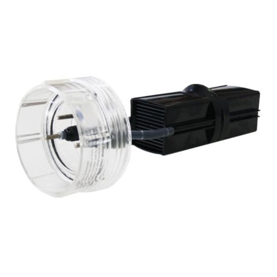
- Page 3 PACKING LIST - Chloromatic ESR and ESC Systems Included with your ESR and ESC systems are the following items, please check the contents of the box carefully prior to attempting to install the system: 1. Power Supply 2. Electrolytic Cell Housing E 3 (a) Electrolytic Cell –...
-
Page 4: Installing The Power Supply
INSTALLATION INSTRUCTIONS FOR CHLOROMATIC ESR and ESC INSTALLING THE POWER SUPPLY: Select a convenient well-ventilated location within one metre of filter equipment and mount the Power Supply vertically onto a post or wall 1.5 metres above ground level. Australian Standards requires that the Power Supply shall not be located within 3 meters of the pool water. - Page 5 PRE - START UP PROCEDURE: Before operating your Chloromatic please ensure the following items have been added to your pool: • SALT - Load salt into the pool at a minimum rate of 40kg per 10,000 litres (0.4%) for ESR systems and 30kg per 10,000 litres (0.3%) for ESC systems.
- Page 6 Once the salt level in the pool is correct the Unit may be switched On. The Stand - by indicator will be On and no Cell Output will be seen for approx 30 seconds, this allows the pump and filter to prime and the Cell Housing to fill with water. After this start - up delay the Display should light up fluctuating around 100, unless in Winter Mode where it will fluctuate around 85.
-
Page 7: System Control
4. PUMP CUT-OUT – The ESC System features a protective interlock system which cuts off power to the pool pump if there is no water flowing through the cell housing. This is especially helpful if the pump ‘runs dry’ and hence may stop the pump motor from burning out. -
Page 8: Winter Mode
LOW SALINITY INDICATOR Your Chloromatic is fitted with a number of protective systems including the Low Salinity Indicator (operation LED’s). As the salt level in the pool decreases, the wear on the Cell increases. Although salt is not consumed in the Chloromatic process, it is lost through splashing, back - washing and on bathers as they leave the pool. -
Page 9: Safety Notice
Automatic Time Clock Operation (optional) If your Power Supply is fitted with an automatic time clock (optional) the operating time(s) can be easily set by pushing the small pins forward or backwards to the desired operating time(s). The unit comes pre-set for 8 hours operation per day. The ON-OFF-AUTO switch functions as follows: AUTO Over-rides automatic time clock, Filtration System switched on. - Page 10 MAINTENANCE OF ELECTROLYTIC CELL: The cell is composed of extremely expensive materials, and although proper maintenance can prolong its life to the maximum, eventually the process of electrolysis will wear away its delicate coating, at which time it gradually ceases to produce chlorine. Mineral salts and calcium (scale) are deposited on the outer and the inner mesh as electrolysis takes place.
-
Page 11: Safety Device
To clean the cell, remove all leads connected to the Head Assembly. Unscrew the Cell by turning the Head Assembly clockwise – as per instructions, and withdraw from the Cell Housing. METHOD 1 Add 1 part HYDROCHLORIC ACID to 5 parts WATER in a suitable container and immerse the Cell in this solution. -
Page 12: Running Times
2. pH AND TOTAL ALKALINITY: A correct pH level must be maintained to prevent problems such as black spot, staining, cloudy water, etc. An incorrect pH level can damage the pool. Correct pH levels are as follows; Fibreglass – 7.0 to 7.4 Other pools – 7.2 to 7.6 If you allow the pH level to rise to 8.0 or above, the chlorine required could be as much as three times the normal amount. -
Page 13: Chlorine Production
CHLORINE PRODUCTION: The Chloromatic must be run daily to generate sufficient chlorine to sanitise the pool. During Summer this is approximately eight hours per day, preferably in two periods - between 6.00 and 8.00am and between 5.00 and 11.00pm. Night time is preferable because chlorine dissipates rapidly in direct sunlight. -
Page 14: General Information
Refer back page of this manual for list of warranty repair agents. Monarch Industries strives to reduce or eliminate any unnecessary expense by producing this Manual. Experience has shown that by following this Manual - in particular the section on Trouble Shooting, approximately 75% of all service calls are unnecessary and the expense and frustration to clients could have been avoided. -
Page 15: Troubleshooting
TROUBLE SHOOTING: No Chlorine Production - Check for 1. Main power outlet switched off 2. Chlorinator not plugged into main outlet 3. Pump not plugged into Chlorinator 4. Time Clock set to Off position/Power switch turned Off 5. System Control turned to mid setting 6, Chlorinator 3 amp fuse blown 7. - Page 16 Please note this page has deliberately been left blank.
Need help?
Do you have a question about the Chloromatic ESR Series and is the answer not in the manual?
Questions and answers