Table of Contents
Advertisement
Quick Links
Advertisement
Table of Contents

Summary of Contents for CellScale MSI9850
- Page 1 MSI9850...
- Page 2 FCC Statement ..............23 Network Description ............23 RF Network Setup .............24 Advanced Modem Settings ..........25 Configuring for multiple networks ........26 Troubleshooting RF Connection Problems .......27 RF Site Testing ..............28 CellScale Network Auto Scan ...........28 3 – S ..........29 ECTION CALE PERATION Power ................29 Multiple Scale Channels ...........29...
- Page 3 5 – RF R .......43 13 – B ............90 ECTION EMOTE ONTROL PTION ECTION Description ................43 Bar Code Setup Menu ............90 Functions ................43 14 – C & C ......92 ECTION HANNEL ETUP ALIBRATION Setting the Transmitter Address ........43 Channel Setup Menu ............92 Contention and Jamming Considerations ......44 Calibrate General Information ..........93 Battery Replacement ............44...
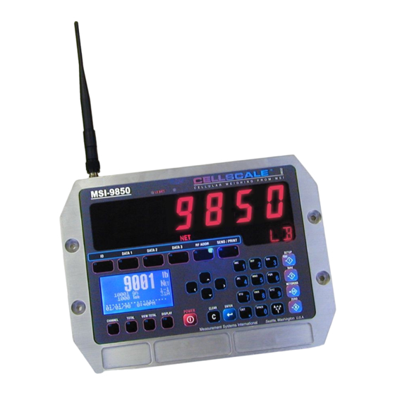
- Page 4 9850's. The backlit, alphanumeric graphic display provides precise, unambiguous indication of operating modes such as Net, Gross, or Total. The 9850 can calibrate a CellScale remotely and provides a user interface to the advanced features of the CellScale. The CellScale system is digitally calibrated from the MSI-3750CS RF Indicator, the MSI-9850, a MSI-9750A Handheld Indicator, or with a terminal program hooked directly to the CellScale model MSI-9000.
- Page 5 . The action of this key is dictated by the Function key menu, but is usually used to send data to the CellScale or one of its hosts. If the Send/Print function is not necessary, any data field or 9850 function can be assigned to this key.
- Page 6 Indicates US short tons equal to 2000 lb. tne – Indicates metric tons equal to 1000 kg. daN – Indicates the force measurement unit dekaNewtons. Dashes indicate data not yet received from the CellScale Host, or the RF network is disconnected. Center of Zero Indicator Units Indicator...
- Page 7 The 9850 is a versatile indicator capable of displaying many data items. As a member of the CellScale family the 9850 does not stand alone. It is a slave device to a CellScale host device. All data displayed on the 9850 is received via RF from a master CellScale.
- Page 8 Reliable 2.4 GHz Frequency Hopping RF communications. Highly immune to interference and multi-path problems. Range in excess of 500 feet indoors (LOS). • Each 9850 can act as a terminal for any CellScale. A 9850 can monitor multiple scale channels on a single CellScale, or multiple scales tied to multiple CellScales. •...
- Page 9 1) Model MSI-9000 CellScale – Rugged unit for interfacing any scale and converting it to RF networking. 2) Model MSI-9008 Multiplexer – Allows up to eight scales with independent calibrations, to share a single CellScale input channel. 3) Model MSI-9020 CellModem – For interfacing peripheral devices to a CellScale.
- Page 10 The 9850 is simple to setup and use. If there are no peripheral devices such as a printer or bar code scanner, setup consists of applying power, and setting the modem controls to talk to a 9000 CellScale. Future Option - Contact MSI for information 1100 LBS NET 5.8 tns Grs...
- Page 11 The standard configuration of the 9850 has the following connectors: 1) Main Power Input – Usually a heavy duty cable for power input. Available also with a connector by special order. AC and DC power modules are available for all industrial voltage sources. 2) Aux Power and Switches (P2) –...
- Page 12 The 9850 is powered by AC or three choices of DC inputs. Universal AC Supply The universal AC Supply is suitable for mains inputs from 86 to 265VAC, 47-440 Hz. The 9850 can be ordered with a standard US Cord (NEMA 5-15 Plug) or an unterminated AC Cord for direct panel wiring or adding a country specific AC Plug.
- Page 13 Brown Connect to Battery or Power Supply Positive (7-25VDC). Again, a direct battery connection is usually best to avoid interference with vehicle electrical systems. The CellScale is internally fused. If connected to a breaker or fuse panel, use 2A at 12V, 1A at 24V. Fast blow or medium blow fuses are acceptable.
- Page 14 The 9850 comes standard with one Comm Port Cable wired for RS-232 (MSI P/N 502513-0001) following the AT standard for 9 pin serial cables (DCE). An unterminated cable is available (MSI P/N 10084) if you wish to wire your own serial cable for RS-232 or RS-422 or RS-485. Comm Ports 1 and 2 are wired identically. Comm Port 1 functions as an RS-232, 422, or 485 port.
- Page 15 The 9850 features a software switchable termina- COMM 1 RS-422/485 tion resistor. 120Ω Termination Resistor Both RS-422 and RS-485 are multi-drop capable. Jumper 1-6-4 The 9850 can drive up to 32 receivers on one twisted pair. Although the 9850 uses standard RS- Black (RD+) 485 drivers, the 9850 firmware does not have a half White (TD+)
- Page 16 The 9850 can directly drive up to 5 external relays which correspond to the CellScale system Set Points 1-5. The open drain MOSFET output lines are transient and inductive kickback protected so that no snubber network is needed for coil relays. The drivers are rated for 5-25Vdc relay coils up to 150mA. The Set Points Port provides a source of 5V, but limit drain from this source to 500mA total maximum.
- Page 17 When the 9850 is DC pow- ered, SP5 can be used since the ground reference is provided through the power input. Standard Opto-isolated Output modules are easily driven by the 9850 Output port. MSI provides a 4 port I/O rack prewired with the Set Points Output Cordset (MSI P/N 10082 + 13186).
- Page 18 Grayhill DC Output Modules 70M-ODC5, 60VDC@3A, Normally-Open 70M-ODC5A, 200VDC@1A, Normally-Open 70M-ODC5B, 60VDC@3A, NO Low off leakage This list represents only a small number of compatible Output Modules. By combining the Set Points Port P3 with the Switch Input Port P2 a complete I/O interface can be realized. Up to 5 Outputs and 4 inputs can be serviced by the 9850 as illustrated.
- Page 19 1) Standard Antenna – This is a small 1/2 wave antenna that mounts directly on the 9000 CellScale enclosure and is suitable for most short to medium range applications. 2) Long Range Antenna – A high gain antenna that is remotely mounted from the 9850 with a low loss coaxial cable. This omnidirectional antenna increases the range up to 4 times.
- Page 20 This Antenna should be vertically oriented. The Long Range Omnidirectional antenna (MSI P/N 12147) is pole mounted (up to 2” diameter) and extends the range of CellScale transmis- sions. MSI supplies this antenna with a 10’ (3m) coax cable pre attached.
- Page 21 2.4GHz. Do not substitute standard coax varieties. A vehicle mount whip antenna is approved for use with MSI CellScale equipment and is available by special order. This 5 dBi gain whip is rugged and waterproof and mounts in a 3/4” (19mm) hole on the roof of mobile vehicles.
- Page 22 Co-Existing with 802.11b Networks In some cases, if a CellScale network is located in close proximity to an 802.11b network, the CellScale network can interfere with the 802.11b network. To avoid causing this interference, the CellScale radio supports a selec- tion of hopping patterns that avoid the various 802.11b direct sequence channels.
- Page 23 The CellScale system uses TDMA (Time Division Multiple Access) to arbitrate between multiple remotes. Each remote is assigned a specific time slot thus guaranteeing data throughput. For more on setting up CellScale net- works, please refer to the MSI-9000 CellScale User Guide.
-
Page 24: Modem Settings
There may be a delay when acquiring a new Master CellScale. If the weight does not appear in 10 seconds, recheck your modem settings at both the 9850 and the master CellScale (or embedded CellScale in a crane scale). -
Page 25: Advanced Settings
The second page also includes a setting making the cellscale 3 Scan Network legal in France. The CellScale master must also have the same setting. DO NOT change the setting in this menu 3 Scan Network without corresponding changes in all CellScale devices in the network. - Page 26 CS address, these must be set up with the “SETUP RF NETWORK” menu and made active. The 9850 can access up to 64 CellScale based Networks. It takes the 9850 from 4 to 8 seconds to switch networks, as it has to sync with a new hopping pattern.
- Page 27 Network numbers. In addition, the CS Address must match on both units. If the Net- work and/or CS Address of the CellScale is in question, you might have to connect a terminal to the CellScale to determine its exact settings.
- Page 28 RF dropout. The location and height of the CellScale master also plays a big part in range so be sure to run the site test with the CellScale in typical locations used in your application.
- Page 29 So, in theory, 1 platform could be calibrated as 8 independent scales. This works because the CellScale does not know or care if a Multiplexer is actually present. It treats the input as a separate scale. The 9850 reads multiple channels by using the Scan list index. The “Scan list” is stored in the CellScale, with up to 32 channels present in the list.
- Page 30 CellScale for the desired channel information. In CellScale systems with multiple channels, you can choose to see more than one channel at a time (See Display Setup in Section 7). In order to zero, tare, or totalize with channels in a multiple channel display, you must first select the channel to operate on.
- Page 31 2) The scale must be stable within the Motion window. The scale will not zero if the motion detect annunciator is on. The CellScale will “remember” that it has a zero request for 2 seconds. If motion clears in that time,...
- Page 32 3) Press to place the value in the Tare Register (Current Channel, current ID). The display reads “TARE SET” when the CellScale responds. All subsequent read- ings have the Tare value subtracted and are displayed in “NET” weight. To View and/or Change the Tare Value 1) In single channel mode, go to step 2.
- Page 33 Tare - Rules for Use: 1) Only positive gross weight readings can be tared. Weight can be tared in both the NET and GROSS modes. When in the NET mode, the TARE is not cumulative, all the weight is tared off (to Net zero). 2) The motion annunciator must be off.
- Page 34 Gross function will affect all meters displaying this channel. Allows easy weight units conversions. Up to 9 Units are available. See “SETUP UNITS” in the CellScale Manual for details on activating the available units. Since Units are stored with each ID Code, the menu item for chang- ing units is found in the “Product ID Codes”...
- Page 35 Starts a display test to observe all display characters. The Info and Weight displays cycle through their character sets. To Start the Display Test 1) Press the key followed quickly by the key. The MSI-9850 startup screen will appear. 2) Press the key.
- Page 36 The 9850 has 10 FUNCTION keys that can be programmed to any of several functions. The default labels are: ID, DATA 1, DATA 2, DATA 3, RF ADDR (Address), SEND/PRINT, CHANNEL, TOTAL, VIEW TOTAL, and DISPLAY. These labels are printed on the front panel. Each key can be programmed for other functions. For example, the TOTAL key can be changed into a UNITS key.
- Page 37 SELECT FOR F4 FROM SELECT FOR F4 FROM SELECT FOR F4 FROM SELECT FOR F4 FROM 1 Misc Functions 1 Data Logging These Menus 2 Set Points 2 Chan, ID, & Address apply to any 3 Bar Codes programmable 3 Total & Statistics key or switch.
- Page 38 Transmit out their respective Comm Ports........R6. Default Function is “Next Channel”. Switches the focus channel to the next active channel in the CellScale Scan List. This is the recommended key to change to “SHIFT” to enable the Remote Shifted Keys.
- Page 39 ....S3. Changes weight units. Scrolls through all enabled units....S4. Starts the Display Test. Cancel by pressing any key on the RF Remote ........S5. Send CS ALL. Causes all programmed Comm Ports on the Host CellScale to output assigned print/data strings.
- Page 40 ...Sends the Aux 1 string directly to Comm Port 1..Sends the Aux 2 string directly to Comm Port 2..Tells the Master CellScale to output its Host 1 output string (CellScale local Comm Port) ...Tells the Master CellScale to output it’s Host3 print string.
- Page 41 ....Observe current status of Set Points. Configure set points....Used to setup CellScale networks and test for adequate range. Starts a packet counter that appears in the lower right corner of the display....Tests the LC and LED Displays. Displays all programmed fonts and symbols.
- Page 42 The “Enter ID String 1” and “Enter ID String 2” function keys provide the user some additional capabilities. When designating a key for these text entry modes, the 9850 brings up a text entry screen that allows you to give a custom 8 character label for the ID String.
- Page 43 Function Key menus and used for any 9850 programmble functions. It does not have the range of the Spread Spectrum modems built into the CellScale equipment and is intended for local control only. Range will vary from 25’ to 100’ depending on room conditions and line of sight to the display. The remote receiving antenna is behind the red lens of the meter and best range will occur when the display is visible to the operator using the RFRC.
-
Page 44: Instruction To The User
The RF Remote Control is a narrow band low power device and does not have the jamming immunity of the Spread Spectrum Modem used by the 9850 to communicate to the Host CellScale. Powerful sources of RF energy in the 418MHz region can jam the remote and prevent it from operating. In this circumstance, trying either of the two other available RF Remote frequencies (433MHz and 315MHz) might solve the problem. - Page 45 ID Codes are created when a new name is entered by the user. The name can be all numbers, all letters, or a combination of numerals and letters. Once the name is entered by the user, the CellScale scans its memory to see if the ID Code already exists.
- Page 46 3) Edit ID Strings – Brings up a submenu for selection of ID Steps through available units String 1 or 2. (defined at CellScale) 4) Edit ID Name – Allows editing the 8 character ID name without PRODUCT ID Chan X-X...
- Page 47 3) Using the numeric keypad enter a name of an existing ID Code. Use the key to select letters as required. If the CellScale detects a match, the existing ID Code will appear. If not, it will create a new one.
- Page 48 To Delete all ID Codes 1) Press , then 2) From the “PRODUCT ID” menu select “Delete ID” 3) From the “Are You Sure” screen press to delete the all the product ID. The Channel will revert to ID1 (default ID) and all other IDs are now gone. Cancel the delete operation by pressing (Setup) or any key other than Memory Full...
- Page 49 CellScale starts a long term, motion compensated (if the motion compensation option is installed in the CellScale), average of the current weight that ends when the weight is dropped. This method is designed for commodity weighing of scrap metal, or other types of materials that are loaded into rail cars, trucks, hoppers, etc., usually with a crane.
-
Page 50: Total Settings
Auto Total Operation 1) Enable the desired Auto Total mode in the “SETUP TOTAL” menu (see “SETUP TOTAL”). Select the “AUTONORM”, “AUTOLOAD”, or the “AUTOPEAK” mode. Exit from the setup menu. 2) Use the key to disable (“TTL OFF”) or enable (“TTL ON”) Auto Total. 3) Place the weight to be totaled on the scale. - Page 51 To Set the Total Mode 1) Press 2) Press the switch or select Total. 3) The current Total Mode is shown on selection 1. 4) Press the key to bring up the “Total Mode Selection” menu. 5) Select the desired Total Mode with the numeric keys ( - ). You are returned to the “Total Status” with the new mode indicated on selection 1.
- Page 52 To Clear the Total Value (Current ID Code only) 1) Press . The current total is displayed. 2) Press . The “ARE YOU SURE” screen gives an opportunity to change your mind. 3) To complete the totaled weight deletion, press the key.
- Page 53 The View Statistics feature uses totaled data from the current ID code in the CellScale to compute statistics. Grand Statistics uses totaled data from all ID codes. Only weight that has been totaled will be used in computing statistics. This procedure requires that F9 is programmed as “VIEW TOTAL”.
-
Page 54: System Settings
When this display indicates “BAD” for the clock 5 Daylite Saving battery, it must be replaced. This requires a disassembly of the 9850. If a CellScale is connected via RF, it will also 5 Daylite Saving report its power status here. - Page 55 This procedure will 7 MORE 8 BACK not erase calibration, which is stored in the CellScale, not the 9850. However, all display modes, text strings, system settings, etc., stored 4 Lock Override in the 9850, will be lost.
-
Page 56: Display Setup
1) Press followed immediately by ). The startup screen will appear. 2) Press the key. A password text entry screen will appear. 3) Using the keypad, input the number 7415369. Press 4) The “ARE YOU SURE” display appears. Press Keyboard lock is provided to prevent casual or accidental pressing of the keys from changing any modes. This function works only from weight display modes. - Page 57 If your CellScale is equipped with multiple channels, the display can be set up to show up to eight channels at once.
- Page 58 IDName-- ... The ID Code name. The name must be programmed by either the CellScale or the 9850. xS or xSL .... The Scan List Index position as stored in the CellScale where x is 1-8. Used on multiple display presets to show which scan list position is included on the preset display.
- Page 59 (SLI). The 9850 reads the scan list out of the master CellScale. If a multi-channel preset is selected that allows more channels than the CellScale has in its scan list, the preset will show just the available channels. If space allows the Date and Time will appear on the bottom line (Line 8).
-
Page 60: Scale Display Setup
The Display Setup Menu provides access to all the display presets, backlight control, function key displays and full display customizing. SCALE DISPLAY SETUP SCALE DISPLAY SETUP Shortcut 1 Single Scale Mode 2 Multi Scale Mode 3 LED Timer 2min 4 LED Brightness 5 LCD Contrast MULTI CH DISPLAY MODE SINGLE SCALE CHANNEL... - Page 61 The 9850 weight display is a primary means of getting and using CellScale data. The user should always select a single channel weight display mode that provides the information needed. When the CellScale is a multi-channel system, a Multi-Channel display mode should also be selected.
- Page 62 However, if one channel is primary, it is easy to distinguish it by making it larger than other channels. In any multi-channel screen, you can display from 2 to 8 channels, assuming that the CellScale Scan List includes at least 8 channels. CellScales with more than eight channels use the page mode to observe all channels.
- Page 63 The 9850 LCD Screen allows a wide variety of scale display screen setups. The illustrations here demonstrate some of the possibilities. The custom display setup menus control the type and placement of available data types. The LCD is a graphics type organized in rows and columns. The row size is fixed at 8 rows of 8 pixels each for a total vertical size of 64 pixels.
- Page 64 The bottom two lines of the Row Setup menu illustrate what the line has programmed into it. Data is displayed in row pairs. For example, while programming row 6, row 5 and 6 will be illustrated. When data from another line is present, as it will be with the large font, the preview area will show as lines.
- Page 65 The custom display setup menus provide access to all the data the scale can provide. When an item is present on the display, it will have an arrow next to its selection number. The length of some data items are fixed, but many have variable lengths.
- Page 66 SCALE DISPLAY SETUP ROW X-X XX CHARACTERS SCALE DISPLAY SETUP ROW X-X XX CHARACTERS 1 Product ID 1 Single Scale Mode 2 Net-Gross-Tare Wt Shortcut 2 Multi Scale Mode 3 Channel Info 3 LED Timer 2min 4 Miscellaneous 4 LED Brightness 5 Date-Time 5 LCD Contrast 1Ø...
- Page 67 SCALE DISPLAY SETUP ROW X-X XX CHARACTER SCALE DISPLAY SETUP ROW X-X XX CHARACTER 1 Product ID Shortcut 1 Single Scale Mode 2 Net-Gross-Tare Wt 2 Multi Scale Mode 3 Channel Info 3 LED Timer 2min 4 Miscellaneous 4 LED Brightness 5 Date-Time 5 LCD Contrast Preview Line...
- Page 68 CellScale and responds as programmed. All 32 Set Points are setup from either the CellScale Terminal Interface, from a 3750CS, 9750A, or from the 9850. All Set Point value parameters are stored in the CellScale and are independent of any other device, including the 9850.
- Page 69 There are four ways to program values, operators, and remote relays for Set Points. 1) Use the Terminal Interface Mode at the CellScale, 2) use a 3750CS, 3) use a 9750A, or 4) use the 9850. To Enter the Set Point Setup Menus 1) Press 2) Select “Set Points”...
- Page 70 Output lists are set in the min = 1 max = CellScale. The output list controls the CellScale ^ incs, v decs digi t response and has no effect on the 9850. 5) Set Point Delay ms – Set point delays are used to...
- Page 71 The 9850 responds to set points in three ways: with an audible alarm, a message display, or a message sent to one or both Comm Ports. These menus program this response. SET POINT AUDIBLE ALARMS SET POINT XX AUDIBLE ALARMS SPXX TRIP F2 VOL...
-
Page 72: Set Point Value
Set Pt Triggers If N/G Wt >= 500.0 uses either the Set Point output controls (which must be AND N/G Wt <=1000.0 set up in the CellScale), or the 9850 Relay Option. Set Pt Resets If N/G Wt < 500.0 OR N/G Wt >... - Page 73 1) Continuously – The Data String can be transmitted continuously at the rate set in the Interval Menu. How fast the weight data updates is determined by the transmission rate in the Master CellScale. “Motion Check” determines if printing is allowed (Motion Check Off) or disallowed (Motion Check On) when the weight is not stable.
- Page 74 (Motion Check On) when the weight is not stable. In addition to the Control modes above, the master CellScale can also force formatted print strings out the Comm Port. See the CellScale manual for more information on Set Point messages and other types of remotely gener- ated messaging.
-
Page 75: Setup Select Menu
SETUP SELECT MENU COMM PORTS & DATA LOG SETUP SELECT MENU COMM PORT 2 1 Function Keys 2 Set Points 1 Comm 1 Mode 485FT Shortcut 3 System 2 Comm 1 8-N-19.2k-HW SETUP SELECT MENU SETUP SELECT MENU 1 Channel & Calibrate 4 Password Locks 3 Comm 2 8-N- 115k-SW... -
Page 76: Parity Bit
An interval of 50 milliseconds means that the scale will output data at the highest rate possible (also limited by the transmission rate from the CellScale). However, a 50ms interval is not guaranteed to have new data on every data output. Interval used with other control modes can be useful for control and monitoring purposes. - Page 77 TRIGGER PRINT ON: The “Trigger Print On’ menu designates the condition that causes the 9850 to output data. The Send / Print key will always work unless specifically locked out or the function key is reassigned. When the designated trigger condition occurs, the print string specified in the “Data Out String” will be output on Comm 2.
- Page 78 1) Use the (ALPHA) key to switch between numeric “1”, upper case “A”, or lower case “a”. The current mode is shown in the lower right corner of the display 2) Press the desired character key. If a “B” is needed, press the key twice.
-
Page 79: Ascii Characters
ASCII CHARACTERS PUNCTUATION MENU ASCII CHARACTERS PUNCTUATION MENU 1 Punctuation 2 Printable Symbols 3 Control Characters 0 F6 Menu 4 Enter Decimal Char ‘ 512 ENT Save 5 Full Screen 9 “ 6 Size SMALL 21/ROW -NAMEofSTRING- Show 83 Characters Toggles between insert cursor &... - Page 80 The 9850 can format virtually any Printer or Serial Data Device including complex bar-code label printers through the use of the built in string formatting. To use this versatile feature, the user must input command codes and data in a specific manner. Each command code consists of a 2 letter mnemonic. Some command codes also require a numeric suffix.
- Page 81 To change a character (highlighted character) Use the LEFT(3), RIGHT (4), UP (5), and DOWN (6) Scroll keys to move around in the print string. Change the cursor into a highlighted character by pressing the key. The flashing digit indicates the edit able character which is also shown in the lower left hand corner of the edit screen (unless you are in full screen mode).
- Page 82 The printer formatting “@” commands and their data configurations are as follows: Description Command Suffix Input Output examples & comments examples *= a space or place holder Select Active Channel where “nn” is the channel Selects Channel List All commands that are c h a n n e l s p e c i f i c a r e list location 01-32 location 5.
- Page 83 Description Command Suffix Input Output examples & comments examples *= a space or place holder Print Modem ID xxx where x is the modem ID from 1-254 Output ID String 1=ID String 1 String 1 from the current ID. ≤20 Bytes. 2=ID String 2 String 2 from the current ID.
- Page 84 Description Command Suffix Input Output examples & comments examples *= a space or place holder Output Weight Value and mode @W 1=current weight **20.002*LB***GROSS* Length: 20, fixed. Leading zeros suppressed 2=gross **205.08*KG***GROSS* Length: 20, fixed. Leading zeros suppressed 3=net *1188.50*G****NET*** Length: 20, fixed.
-
Page 85: Data Logging
The 9850 has two battery backed memory locations for storing scale data. Predefined function keys are available for storing user configured data directly to either memory location. Data Logging uses the “Main Data String” and “Aux String” to store user defined data at the press of a button. Usually the “Main Data String” is programmed with the weight configured as desired. - Page 86 1) Output Memory 1 – Pressing will output all data in Data Logging Memory 1 to Comm Port 1. Connect the 9850 to an appropriate terminal or computer before using this function. 2) Output Memory 2 – Pressing will output all data in Data Logging Memory 2 to Comm Port 1. Connect the 9850 to an appropriate terminal or computer before using this function.
- Page 87 SETUP SELECT MENU SETUP SELECT MENU Shortcut to Comm Menus COMM PORTS & DATA LOG COMM PORT 2 1 Function Keys SETUP SELECT MENU SETUP SELECT MENU 2 Set Points 1 Comm 1 Mode 485FT 1 Channel & Calibrate 2 Display 3 System 2 Comm 1 8-N-19.2k-HW...
- Page 88 In order for a host to send a message to an individual 9850, the host must know the address of the 9850. The string required for the host to transmit through a CellScale modem is: Where xxx is replaced by the address of the 9850. It is not necessary to use three digits if the address is smaller.
- Page 89 More than 1 Function key can be designated for messages and the user can choose to send to a specific CellScale RF or direct port or set it to reply to the last modem that sent a message.
- Page 90 The Bar Code features of the 9850 allow the user to add scanned data to weight readings and trigger transmis- sions directly into RF connected computers. In combination with the Data Logging features, bar code scans can trigger data storage for uploading later. Bar Code data is directed into text fields under user control.
- Page 91 Bar Code 1 (BC1). 3 CS RF Host 3 4 CS RF Host 4 Selecting 1 will send the data to the master CellScale’s 5 CS RF Host 5 Comm Port 1. BC1 data will be sent to all of the...
- Page 92 ESC exits no change Legal-for-Trade (LFT) systems until the calibration switch ENTER saves value 0-9 replaces value is enabled at the CellScale. Advanced settings for filtering must be performed in the Master CellScale. min = 0 max = Calibrate Settings – See following submenu description.
- Page 93 The following sections are intended for qualified scale technicians. The CellScale can be calibrated either directly using the Terminal Interface mode, or by using a 9850, 9750A, or 3750CS. See the CellScale operators guide for information on direct calibration. This section details the calibration of a CellScale using the 9850 RF Remote Indicator.
- Page 94 When the weight Unload scale. Press ENTER when stable. is stable press ESCape ends Cal. 11) “SPAN CALIBRATION 2” – Now that the CellScale has 1 span SPAN CALIBRATION SPAN CALIBRATION 1 Scale = -XXXXXXX- point, it transmits back the current reading.
- Page 95 The motion band determines the range of weight variation that the indicator considers to be stable weight. Since the CellScale will not zero or tare a value in motion, the motion band directly influences the accuracy of the scale system. The motion band in Legal-For-Trade systems is usually limited to ≤ 0.6d but sometimes up to ±3d in certain types of installations.
- Page 96 The COZ indicator turns on when the scale is within 1/4 d of the last zero setting. Some legal-for-trade jurisdic- tions require its use. To Enable/Disable the COZ Indicator 1) Press , then 2) Select “Calibration Settings” 3) Toggle the Center of Zero indicator on or off with the key.
- Page 97 (5) 115200 11) In this example, choose 57.6K baud. This will immediately change the baud rate of the CellScale. It will transmit the MAIN MENU again, but until the terminal Baud Rate is changed, the transmission will be garbage. Change the baud rate of your terminal program to match. Then press to refresh the display.
- Page 98 12) Choosing “Update software” will start with erasing the current program with the following screen on the terminal. Please wait for complete erased of flash chip application sectors. TC58FVM5B2A Erasing Sector: ....13) When the Flash memory is completely erased, the 9850 will request that the new file be uploaded. Use the terminal upload utility (part of your terminal program) to send the MSI supplied S-Record file.
-
Page 99: Setup Select Menu
SETUP SELECT MENU SETUP SELECT MENU 1 Function Keys 2 Set Points 3 System SETUP SELECT MENU PASSWORD LOCKS PASSWORD LOCKS SETUP SELECT MENU 4 Password Locks 1 Function Keys 5 Bar Code 2 Set Points 1 Change Password 6 Options 3 System 2 Status LOCKED... - Page 100 SETUP SELECT MENU FUNCTION KEY ASSIGNS KEY GROUP SETUP SELECT MENU 1 Function Keys 2 Set Points 1 Function Keys 1-10 3 System 2 Enter Fcn Keys 1-10 4 Password Locks 3 External Switches 5 Bar Code 4 RF Remote 1-7 6 Options 5 Shift RF Remote 1-7 7 MORE...
- Page 101 SETUP SELECT MENU COMM PORTS & DATA LOG SETUP SELECT MENU COMM PORT 2 1 Function Keys 2 Set Points 1 Comm 1 Mode 485FT Shortcut 3 System 2 Comm 1 8-N-19.2k-HW SETUP SELECT MENU SETUP SELECT MENU 1 Channel & Calibrate 4 Password Locks 3 Comm 2 8-N- 115k-SW...
- Page 102 COMM PORT 1 COMM PORTS & DATA LOG 2 or 3 Key COMM PORT 2 COMM PORT 2 2 Key shown for example 1 Enter/Edit Strings 1 Comm 1 Mode 485FT 2 Output Interval 2 Comm 1 8-N-19.2k-HW 3 Comm 2 8-N- 115k-SW 3 Control Settings 4 Serial Settings...
- Page 103 SETUP SELECT MENU SETUP SELECT MENU Shortcut to Comm Menus COMM PORTS & DATA LOG COMM PORT 2 1 Function Keys SETUP SELECT MENU SETUP SELECT MENU 2 Set Points 1 Comm 1 Mode 485FT 1 Channel & Calibrate 3 System 2 Display 2 Comm 1 8-N-19.2k-HW...
- Page 104 -ID String 2- BAR CODE IS SENT TO BAR CODE X IS SENT TO 4 Copy prev String 2 1 CellScale Comm 1 2 All CS Outputs 3 CS RF Host 3 4 CS RF Host 4 5 CS RF Host 5...
- Page 105 = 0, max = min = Ø, max = ^ incs, v decs value ^ incs, v decs value CELLSCALE ADDRESS CELLSCALE ADDRESS 802.11b AVOIDANCE ESC exits no change 1 OFF, FCC/ETSI LEGAL ENTER saves value 2 Bands 1 & 2 0-9 replaces value 3 Bands 3 &...
-
Page 106: Scale Display Setup
SCALE DISPLAY SETUP SCALE DISPLAY SETUP Shortcut 1 Single Scale Mode 2 Multi Scale Mode 3 LED Timer 2min 4 LED Brightness 5 LCD Contrast MULTI CH DISPLAY MODE MULTI CH DISP MODE SINGLE SCALE CHANNEL SINGLE SCALE CHANNEL 0 Number of Chans DISPLAY MODE DISPLAY MODE 1 3 Ch - 1 lg, 2 sm... - Page 107 SCALE DISPLAY SETUP ROW X-X XX CHARACTERS SCALE DISPLAY SETUP ROW X-X XX CHARACTERS 1 Product ID 1 Single Scale Mode 2 Net-Gross-Tare Wt Shortcut 2 Multi Scale Mode 3 Channel Info 3 LED Timer 2min 4 Miscellaneous 4 LED Brightness 5 Date-Time 5 LCD Contrast 1Ø...
- Page 108 SCALE DISPLAY SETUP ROW X-X XX CHARACTER SCALE DISPLAY SETUP ROW X-X XX CHARACTER 1 Product ID Shortcut 1 Single Scale Mode 2 Net-Gross-Tare Wt 2 Multi Scale Mode 3 Channel Info 3 Backlight 2min 4 Miscellaneous 4 Backlight level 5 Date-Time 5 Contrast Preview Line...
-
Page 109: Channel / Calibration
CHANNEL / CALIBRATION 1 Channel is ACTIVE CHANNEL / CALIBRATION --Channel Name-- --Channel Name-- --Chn-- --Index-- --Chn-- --Index-- 1 Channel INACTIVE 1 Channel is ACTIVE Shortcut 2 Filter 3 Calibrate Settings CHANNEL FILTER CHANNEL FILTER 4 Start Calibration 5 Zero RUSure Msg ON 1 Off 2 Low 3 High... - Page 110 AUTOMATIC SHUTDOWN AUTOMATIC SHUTDOWN 3 Sel Aux Pwr = 5.5V Clock & RAM = GOOD 1 Off in 5 minutes CellScale = GOOD 2 Off in 30 minutes 9850 Int Temp is 56°C 3 Off in 1 hour Light Reading...
- Page 111 CHANNEL / CALIBRATION CHANNEL / CALIBRATION --Channel Name-- --Channel Name-- --Chn-- --Chn-- --Index-- --Index-- 1 Channel is ACTIVE Shortcut 2 Filter 3 Calibrate Settings 4 Start Calibration 5 Zero RUSure Msg Changes to the next Channel available 4 CalibrationDisabled CALIBRATION UNITS CALIBRATION UNITS 1 Pounds 2 Kilograms...
- Page 112 ASCII CHARACTERS PUNCTUATION MENU ASCII CHARACTERS PUNCTUATION MENU 1 Punctuation 2 Printable Symbols 3 Control Characters 0 F6 Menu 4 Enter Decimal Char ‘ 512 ENT Save 5 Full Screen 9 “ 6 Size SMALL 21/ROW -NAMEofSTRING- Show 83 Characters Toggles between insert cursor &...
- Page 113 Input Set Point MASTER SET POINTS PROGRAM SET POINT MASTER SET POINTS PROGRAM SET POINT 1 SP XX -SPName- # for programming ESC exits no change 2 9850 Response (1-32) 1 Program Set Point ENTER edits value 3 Input Source 2 Set Points ENABLED Ø-9 replaces value...
- Page 114 Go to Index...
- Page 115 Current String Length Maximum String Length (varies from 8 to 512 bytes) 0 F6 Menu Highlighted Character 512 ENT Save (Shows character being edited) -NAMEofSTRING- -NAMEofSTRING- Cursor Position Keyboard Mode 1=Numerals String Name A=Upper Case Alphanumeric a=Lower Case Alphanumeric Numeric Alpha Key “1”...
- Page 116 Operating / Storage (Internal AC/DC Power): and append the bar code data to weight, date, and time data gener- ated by the CellScale. Pass thru data can be sent directly to host -20°C to +70°C (-4°F to 158°F) computers via MSI RF modems. 5Vdc @ 500mA is available for Operating / Storage (DC Power): powering Bar Code Readers.
- Page 117 MEASUREMENT SYSTEMS INTERNATIONAL, INC., WARRANTS load sensing elements and meters against defects in workmanship and materials for a period of one year from date of purchase and warrants electrical cables and batteries against the same defects for a period of ninety (90) days from date of purchase. Any device which proves defective during the warranty period will be replaced or repaired at no charge;...