Advertisement
- 1 Introduction
- 2 What's in the box
- 3 Requirements
- 4 Overview
- 5 Home viewer overview
- 6 How the system works
- 7 Protect your privacy and online security
- 8 Connect
- 9 Insert micro SD card
- 10 Set up your wireless monitoring system
- 11 Test the location for the camera units
- 12 Mount the camera unit (optional)
- 13 Connect to audio output device (optional)
- 14 Pair new camera unit
- 15 General product care
- 16 Storage
- 17 Frequently asked questions
- 18 Technical specifications
- 19 Documents / Resources
Introduction
Go to www.vtechphones.com for support and the latest VTech product news.
Before using this 2 Camera Wireless Monitoring System, please read the Important safety instructions.
For support, shopping, and everything new at VTech, visit our website at www.vtechphones.com.
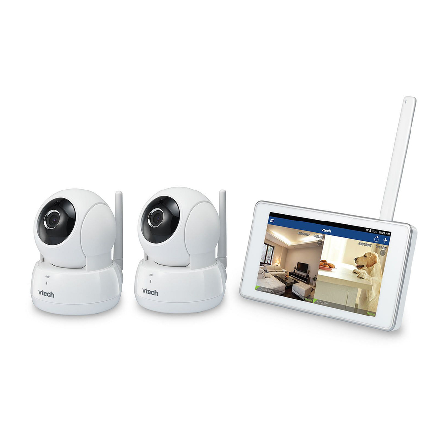
VTech 2 Camera Wireless Monitoring System allows you to keep an eye on your areas when you are on the move or away.
This monitoring system is Wi-Fi enabled, which uses your home wireless network to stream live video and audio through the HD camera units and 5-inch touch screen home viewer.
You can also monitor your areas from your smartphone and mobile tablet.
VTech 2 Camera Wireless Monitoring System uses MyVTech Cams app to let you instantly see and hear what's happening in your areas from anywhere in the world.
The app can be the App Store or the Google PlayTM Store, directly from your smartphone or mobile tablet.
What's in the box
Your 2 Camera Wireless Monitoring System package contains the following items. Save your sales receipt and original packaging in the event warranty service is necessary.


Requirements
Make sure your system includes the following components, and they meet the minimum requirement.
| Network | Wi-Fi |
| Wi-Fi router | 2.4GHz IEEE 802.11 b/g/n |
| Internet connection | At least 1.0 Mbps upload bandwidth per camera |
| micro SD card | Support Class 4 or higher, with storage capacity up to 32GB |
| Smartphones/tablets (for remote access) |
|
| Video codec (for remote access) | H.264 |
Overview
HD Pan/tilt camera overview

- Light sensor
- Infrared LEDs
- Allow you to see clearly in a dark surrounding.
- Camera lens
- Microphone
- Antenna
- Connect to router with Wi-Fi.

- Speaker
- Power jack
- Ethernet port
- Connect to router with a RJ45 network cable (optional).
- 3.5mm line jack
- Connect to audio output device (optional).
- micro SD card slot
- Online LED indicators
- Flash orange and blue alternately when the camera unit is in pairing mode.
- Orange is steady on when the camera unit is connecting to the Internet.
- Orange and blue are steady on when the camera unit is idle.
- Flash orange and blue slowly during video streaming.
- Flash orange and blue quickly and alternately when the camera unit is updating its firmware.
![]() TIP
TIP - You can turn off the camera's LEDs if you find them too bright. Read the Online LED indication section under Camera settings in your home viewer's app manual for instructions.
- Volume –
- Press to decrease the speaker volume.
- Volume +
- Press to increase the speaker volume.

- Pair/reset button
- Press and hold for three seconds to enter pairing mode.
Home viewer overview


| 1 | + / VOL / -
|
| 2 |

|
| 3 | 5-inch touch screen monitor
|
| 4 | Microphone |
| 5 | Antenna |
| 6 | Speaker |
| 7 |  micro SD card slot micro SD card slot |
| 8 | RESET
|
| 9 |  3.5mm audio jack 3.5mm audio jack
|
| 10 |  Micro USB 2.0 port Micro USB 2.0 port
|
How the system works
The Wi-Fi router (not included) provides Internet connectivity to your wireless monitoring system. It serves as a communicating channel between your camera units and home viewer, allowing you to monitor and/or control your camera units wherever you are.

Protect your privacy and online security
VTech cares about your privacy and peace of mind. That's why we've put together a list of industry-recommended best practices to help keep your wireless connection private and your devices protected when online. We recommend you carefully review and consider complying with the following tips.
Ensure your wireless connection is secure.
- Before installing a device, ensure your router's wireless signal is encrypted by selecting the "WPA2-PSK with AES" setting in your router's wireless security menu.
Change default settings.
- Change your wireless router's default wireless network name (SSID) to something unique.
- Change default passwords to unique, strong passwords. A strong password:
- Is at least 10 characters long.
- Is complex.
- Does not contain dictionary words or personal information.
- Contains a mix of uppercase letters, lowercase letters, special characters and numbers.
Keep your devices up to date.
- Download security patches from manufacturers as soon as they become available. This will ensure you always have the latest security updates.
- If the feature is available, enable automatic updates for future releases.
Disable Universal Plug and Play (UPnP) on your router.
- UPnP enabled on a router can limit the effectiveness of your firewall by allowing other network devices to open inbound ports without any intervention or approval from you. A virus or other malware program could use this function to compromise security for the entire network.
For more information on wireless connections and protecting your data, please review the following resources from industry experts:
- Federal Communications Commission: Wireless Connections and Bluetooth Security Tips – www.fcc.gov/consumers/guides/how-protect- yourself-online.
- U.S. Department of Homeland Security: Before You Connect a New Computer to the Internet – www.us-cert.gov/ncas/tips/ST15-003.
- Federal Trade Commission: Using IP Cameras Safely – https://www.consumer.ftc.gov/articles/0382- using-ip-cameras-safely.
- Wi-Fi Alliance: Discover Wi-Fi Security – http://www.wi-fi.org/discover-wi-fi/security.
Connect
You can choose to set up the camera units for desktop usage, wall mounting or ceiling mounting.
 NOTES
NOTES
- Use only the camera power adapters supplied with this product.
- Make sure the electrical outlets are not controlled by wall switches.
- The power adapters are intended to be correctly oriented in vertical or floor mount positions. The prongs are not designed to hold the plug in place if it is plugged into a ceiling, under-the-table or cabinet outlet.
- Make sure the camera units and the power adapter cords are out of reach of children.
Connect the Camera units
Wi-Fi connection
NOTES
- Before you connect the camera units, make sure you have Internet access and a Wi-Fi router (IEEE 802.11 b/g/n). Data charges apply and service plan may vary for Internet access. Router is not included.
- Do not plug in the network cable.
- To maintain compliance with the FCC's RF exposure guidelines, place the HD camera at least 20cm from nearby persons.
- Connect the power adapter to the camera unit and a power supply.

- Place the camera unit at a desired place.


NOTE
- To turn off the camera unit, unplug the camera from the power supply.
Cable connection (optional)
After you have paired the camera units with your home viewer via Wi-Fi, you can connect the camera units to the Internet using the network cables to optimize your Internet connection. Refer to the online app manual for the instructions on how to pair your camera units with your home viewer.
")
Connect and charge the home viewer

NOTES
- The home viewer is fully charged after three hours of continuous charging.
- It takes longer to charge when the home viewer is turned on. To shorten the charging time, turn the home viewer off while charging.
- The standby time varies depending on your actual use.
After the home viewer is fully charged, press and hold ![]() to power on.
to power on.

The battery icon indicates the battery status (see the following table).
| Battery indicators | Battery status | Action |
The screen displays  . . |
The battery has very little charge and may be used for only a short time. | Charge without interruption (about 30 minutes). |
The battery icon becomes solid  . . |
The battery is fully charged. | To keep the battery charged, connect it to AC power when not in use. |
Insert micro SD card
Insert micro SD card into the camera units (recommended)
Your camera units can capture videos of the monitoring area when motion is detected. You can choose to save the videos to a micro SD card.
NOTE
- Your camera units support Class 4 or higher micro SD cards, with each storage capacity up to 32GB.

- Prior to inserting or ejecting the micro SD card, the camera unit must be powered off. To power off, unplug the camera unit from the power supply.

Insert micro SD card into the home viewer (optional)
Your home viewer comes with 4GB internal flash memory that allows you to store snapshots captured and videos recorded manually with your cameras. You can also insert a micro SD card into the home viewer for more storage capacity.
NOTE
- Some of the internal flash memory will be occupied by the home viewer's operating system and data storage. The actual memory available will be less than 4GB.


Set up your wireless monitoring system
After you have connected the home viewer and the camera units, refer to the Quick start guide included in your package to set up your wireless monitoring system.
2 Camera Wireless Monitoring System setup:
- Set up Wi-Fi connection
- Add cameras
Test the location for the camera units
Before you install your camera units, you need to test which of your selected monitoring areas within the house have good Wi-Fi signal strength. After you have connected your home viewer to a Wi-Fi network, you can use your home viewer's Wi-Fi signal strength indicator to assist in checking.
Once you have identified a suitable location, you can install your camera unit. Adjust the distance between your camera units and the Wi-Fi router if needed.
![]() TIP
TIP
- Depending on surroundings and obstructing factors, such as the effect distance and internal walls have on signal strength, you may experience reduced Wi-Fi signal. To improve the Wi-Fi signal strength, adjust the distance or direction of your home viewer. Check with your home viewer again.

Mount the camera unit (optional)
- Place the wall mount bracket on a wall or on the ceiling, and then use a pencil to mark two holes in parallel.
 - Step 1")
- Remove the wall mount bracket and then drill two holes in the wall or on the ceiling (7/32" drill bit).
- If you drill the holes into an object other than a stud, insert the wall anchors into the holes and tap gently on the ends with a hammer until the wall anchors are flush with the wall.
- Align the holes on the wall mount bracket with the screws on the wall or on the ceiling. Tighten the screws in the holes.
- Step 2")
- Place the camera unit on the wall mount bracket, and then slide it forward until it locks into place.
 - Step 3")
-OR-
 - Step 4")
- Connect the power adapter to the camera unit and a power supply not controlled by a wall switch.
 - Step 5")
 - Step 1")
- Step 2")
 - Step 3")
 - Step 4")
 - Step 5")
Connect to audio output device (optional)
The camera unit has a built-in speaker. You can also connect an external self-powered speaker to your camera unit for extra sound quality.
")
Pair new camera unit
You can add or replace any camera units to your 2 Camera Wireless Monitoring System.
The wireless monitoring system family includes HD cameras VC921 and VC931, which can be purchased separately. They can be cross-paired within the family, for example, you can have a combination of VC921 and VC931. You can pair a maximum of four HD camera units to your home viewer.
For more details, refer to the online app manual of your wireless monitoring system (VC921 or VC931) in the Help page of your home viewer.
NOTE
- Your home viewer can pair and access a maximum of four camera units. You can add more camera units to your wireless monitoring system using the MyVTech Cams mobile app. Download the mobile app and create a user account. Then, you can pair your existing camera units in your home viewer and pair additional camera units to your user account using the mobile app. The mobile app can pair and access up to 10 camera units. The additional camera units can only be paired and accessed via the mobile app.
General product care
To keep this product working well and looking good, follow these guidelines:
- Avoid putting it near heating appliances and devices that generate electrical noise (for example, motors or fluorescent lamps).
- DO NOT expose it to direct sunlight or moisture.
- Avoid dropping the product or treating it roughly.
- Clean with a soft cloth.
- DO NOT immerse the camera unit in water and do not clean it under the tap.
- DO NOT use cleaning spray or liquid cleaners.
- Make sure the camera unit is dry before you connect it to the mains again.
Storage
When you are not going to use the wireless monitoring system for some time, store the home viewer, the camera units, and the adapters in a cool and dry place.
Frequently asked questions
Below are the questions most frequently asked about the wireless monitoring system. If you cannot find the answer to your question in the below table, visit our website at www.vtechphones.com or call 1-844-848-8324 (1-844-84-VTECH) for customer service.
The LEDs on the camera unit are too bright. Can I turn them off? |
You can turn off the LEDs of your camera units. Read the Online LED indication section under Camera settings in your home viewer's app manual for instructions. |
Why does the HD camera not respond normally? |
Try the following (in the order listed) for common cure:
|
Why is my screen in black and white? |
The HD camera unit has a light sensor that measures the ambient light. When the ambient light is dim, such as during nighttime or in a dark room, the camera activates its infrared LEDs, and displays the camera view in black and white. |
Why does my HD camera show offline?Why is the connection lost every now and then? |
The camera unit may lose the Internet connection. Check your network and the router setting. |
| Other electronic products may cause interference with your HD cameras. Try installing your HD cameras as far away from these electronic devices as possible. |
Technical specifications
| Frequency | Camera unit: 2412 - 2462 MHz |
| Channels | 11 |
| LCD | 5'' Color LCD (IPS 480x854 pixels) |
| Nominal effective range | Maximum power allowed by FCC and IC. Actual operating range may vary according to environmental conditions at the time of use. |
| Power requirement |
Input: 100-240V AC 50/60Hz Output: 5V DC 1500mA |
Google Play TM is a trademark of Google Inc.
App Store is a trademark of Apple Inc., registered in the
U.S. and other countries.

 Specifications are subject to change without notice.
© 2017 VTech Communications, Inc.
All rights reserved.

Documents / ResourcesDownload manual
Here you can download full pdf version of manual, it may contain additional safety instructions, warranty information, FCC rules, etc.
Download VTech VC9312-245 - 2 Camera Wireless Monitoring System Installation
Advertisement


Need help?
Do you have a question about the VC9312-245 and is the answer not in the manual?
Questions and answers