Table of Contents
Advertisement
Quick Links
IPC-Q37MF / IPC-C24MF
Series User's Manual
No. G03-IPC-Q37MF Rev: 1.0
Release date: July 14, 2020
Trademark:
* Specifications and Information contained in this documentation are furnished for information use only, and are
subject to change at any time without notice, and should not be construed as a commitment by manufacturer.
Advertisement
Table of Contents

Subscribe to Our Youtube Channel
Related Manuals for Fodenn IPC-Q37MF Series

Summary of Contents for Fodenn IPC-Q37MF Series
- Page 1 IPC-Q37MF / IPC-C24MF Series User’s Manual No. G03-IPC-Q37MF Rev: 1.0 Release date: July 14, 2020 Trademark: * Specifications and Information contained in this documentation are furnished for information use only, and are subject to change at any time without notice, and should not be construed as a commitment by manufacturer.
-
Page 2: Table Of Contents
TABLE OF CONTENT ENVIRONMENTAL SAFETY INSTRUCTION ............... iii ENVIRONMENTAL PROTECTION ANNOUCEMENT ............iii USER’S NOTICE ........................iv MANUAL REVISION INFORMATION ................... iv ITEM CHECKLIST ........................ iv CHAPTER 1 INTRODUCTION OF THE MOTHERBOARD SPECIFICATION ....................1 LAYOUT DIAGRAM ....................2 CHAPTER 2 HARDWARE INSTALLATION JUMPER SETTING .................... -
Page 3: Environmental Safety Instruction
Environmental Safety Instruction Avoid the dusty, humidity and temperature extremes. Do not place the product in any area where it may become wet. 0 to 40 centigrade is the suitable temperature. (The figure comes from the request of the main chipset) ... -
Page 4: User's Notice
USER’S NOTICE COPYRIGHT OF THIS MANUAL BELONGS TO THE MANUFACTURER. NO PART OF THIS MANUAL, INCLUDING THE PRODUCTS AND SOFTWARE DESCRIBED IN IT MAY BE REPRODUCED, TRANSMITTED OR TRANSLATED INTO ANY LANGUAGE IN ANY FORM OR BY ANY MEANS WITHOUT WRITTEN PERMISSION OF THE MANUFACTURER. -
Page 5: Chapter 1 Introduction Of The Motherboard
*Note: SIMCARD slot only work when compatible Nano SIM card installed & 3G/4G/5G LAN card module installed in M2B slot. IPC-Q37MF Series: 6*SATAIII 6Gb/s port support RAID 0/1/5/10 (SATA1~SATA6, SATA6 co-lay M2M slot) IPC-C24MF Series: 8*SATAIII 6Gb/s port support RAID 0/1/5/10... -
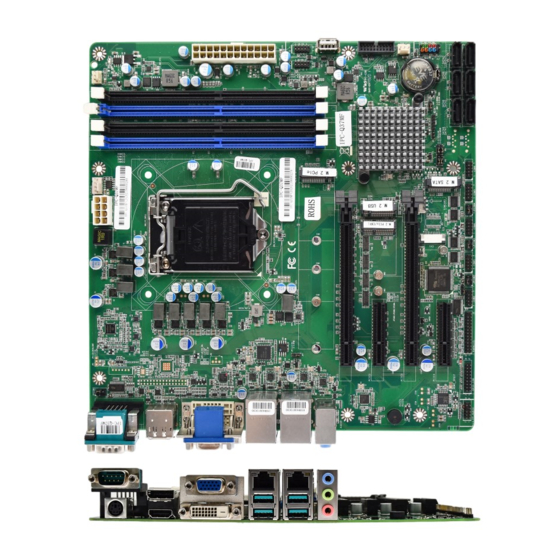
Page 6: Layout Diagram
4* USB 3.1 (Gen.2) port 2* RJ-45 LAN port 1*3-phone audio jack (Line-in, Line-out, MIC) Internal I/O Connectors & Headers: 1*24-pin main power connector 1 *8-pin 12V power connector 1* CPUFAN connector & 2* SYSFAN connector ... - Page 7 Motherboard Internal Diagram IPC-Q37MF Series: CPUFAN SYSFAN1 Connector Connector *INVERTER (Option) ATX 12V DDR4 Power Connector *LVDS Header DIMM Slot x 4 (Option/Col-ay VGA) LGA 1151 *Rear IO CPU Socket Connector (Refer to Page-2) ATX Power Connector PCI Express x16 Slots (*PCIE1/3) USB 2.0 Headers...
- Page 8 IPC-C24MF Series: SYSFAN1 CPUFAN Connector Connector *INVERTER (Option) ATX 12V Power Connector DDR4 *LVDS Header DIMM Slot x 4 (Option/Col-ay VGA) LGA 1151 *Rear IO CPU Socket Connector (Refer to Page-2) ATX Power Connector PCI Express x16 Slots (PCIE1/3) USB 2.0 Headers M.2 M-Key Slot (NVM2M) USB 2.0 Port...
- Page 9 Motherboard Jumper Position: JPCOM1 *JP5 (Option) *JP6 (Option) COPEN JATX_AT JPCOM3 JBAT JPCOM2 JPCOM4 *Note: The diagrams in the manual are mostly taken from IPC-C24MF series unless otherwise stated. Jumper Jumper Name Description JPCOM1 COM1 Port Pin9 Function Select 4-pin Block JPCOM2 COM2 Header Pin9 Function Select 4-pin Block...
- Page 10 JP5 (Option) LVDS LCD Backlight VCC Select 3-pin Block JP6 (Option) LVDS LCD Panel VCC Select 4-pin Block Connectors Connector Name COM1 RS232/422/485 Serial Port Connector PS2 Keyboard & Mouse Combo Port DP_HDMI Top: Display Port Connector Bottom: High-Definition Multimedia Interface Connector CRT+DVI Top: VGA Port Connector...
-
Page 11: Chapter 2 Hardware Installation
Chapter 2 Hardware Installation 2-1 Jumper Setting JPCOM1 (4-pin): COM1 Port Pin9 Function Select JPCOM1 COM1 → JPCOM 1 COM 1 Port Pin-9 2-4 Closed: 3-4 Closed: 4-6 Closed: RI=RS232; RI= 5V; RI= 12V; JPCOM2 (4-pin): COM2 Header Pin9 Function Select →... - Page 12 JPCOM4 (4-pin): COM4 Header Pin9 Function Select → JPCOM 2 COM 4 Header Pin-9 2 4 6 2 4 6 2 4 6 1 3 5 1 3 5 1 3 5 JPCOM4 3-4 Closed: 2-4 Closed: 4-6 Closed: RI= 5V; RI=RS232;...
- Page 13 JP2 & JP3 (3-pin): M2M Slot/SATA6 Function Select → M 2M Slot /SATA6 Select JP2 &JP3 2 4 6 1 3 5 JP2 & JP3 (1-3) (2-4)Closed:M2M Slot; 2 4 6 2 4 6 1 3 5 1 3 5 JP2 &...
- Page 14 Pin 1-2 Short: When Case open function pin short to GND, the Case open function was detected. When Used, needs to enter BIOS and enable ‘Case Open Detect’ function. In this case if your case is removed, next time when you restart your computer, a message will be displayed on screen to inform you of this.
-
Page 15: Connectors And Headers
Connectors and Headers 2-2-1 Rear I/O Back Panel Connectors COM1 RS232/422/485 RJ-45 LAN Ports Serial Port Display Port VGA Port Line-In Line-Out PS/2 Keyboard & Mouse Combo Port HDMI Port USB3.1 (Gen.2) DVI-D Port Ports Icon Name Function Mainly for user to connect external MODEM or RS232/422/485 other devices that supports Serial Port... -
Page 16: Motherboard Internal Connectors
COM1 (9-pin Block): RS232/422/485 Port COM1: RS232/422/485 Serial Port; The pin assignment for RS-232/ 422/ 485 is listed as follows: 1 2 3 4 5 Pin1 Pin1 Pin1 6 7 8 9 RS422 Mode RS485 Mode RS232 Mode COM1 port can function as RS232/422/485 port. In normal settings COM1 functions as RS232 port. - Page 17 ROW1 ROW2 +3.3V +3.3V +3.3V -12V Soft Power on Power OK +5V Stand by +12V +12V +3.3V 24-pin Main Power Connector Figure1:20-pin power plug Figure 2:24-pin power plug (2) ATX12V (8-pin block): 12V Power Connector This is a new defined 8-pin connector that usually comes with ATX Power Supply that supports extra 12V voltage to maintain system power consumption.
- Page 18 (3) CPUFAN (4-pin): CPU Fan Connector CPUFAN Pin1 (4) SYSFAN1 (3-pin): System Fan1 Connector SYSFAN1 Pin1 (5) SYSFAN2 (3-pin): System Fan2 Connector Pin1 +12V Fan Power Fan Speed SYSFAN2...
- Page 19 (6) SATA1~SATA8(7-pin): SATAIII Port connector SATA7 & SATA8 are only optional for IPC-C24MF series. This is a high-speed SATAIII port that supports 6GB/s transfer rate. *SATA6 SATA4 Pin No. Definition SATA8 (Option) SATA2 SATA3 SATA7 (Option) SATA5 SATA1 *Note: SATA6 port co-lay with M2M, type-2242 slot; these two interfaces cannot function at the same time, user can choose one of them to work via JP2 &JP3 jumper.
- Page 20 NVM2M Slot Installation Guide: 1. Prepare compatible M.2 SATA or M.2 SSD card. Deferent type of cards has different length. Find corresponding nut location for further installation. Nut Location Card Length 4.2 cm 6 cm 8 cm 11 cm Module Type Type- 2242 Type- 2260 Type- 2280...
-
Page 21: Header Pin Definition
(8) Dual Channel Memory Installation: Configuration DIMM1 DIMM2 DIMM3 DIMM4 install install install install install install install install Notice! For dual channel installation, you need to install the same brand, speed, size and type memory module. It is unable to activate dual channel feature if you install one or three memory modules, or you install DIMM1 &... - Page 22 (2) FP_USB1/FP_USB2(9-pin): USB 2.0 Port Headers FP_USB2 FP_USB1 Pin 1 -DATA -DATA +DATA +DATA (3) FP_USB30(19-pin): USB 3.1(Gen.1) Port & USB 2.0 Port Header Pin1 USB3_P5_RXN USB3_P5_RXP FP_USB30 USB3_TXN5 USB3_TXP5 USB2_P11_N USB2_P6_N USB2_P11_P USB2_P6_P 11 10 (4) FP_AUDIO (9-pin): Line-Out, MIC-In Header This header is connected to Front Panel Line-out, MIC connector with cable.
- Page 23 (5) GPIO_CON (18-pin): 16-Bit GPIO Header Pin1 GPIO_CON (6) PARALLEL (25-pin): Parallel Port Header Pin2 PARALELL Pin1 Pin NO. Pin Definition Pin NO. Pin Definition Pin 1 STB- Pin 2 AFD- Pin 3 Pin 4 ERR- Pin 5 Pin 6 INIT- Pin 7 Pin 8...
- Page 24 (7) COM2/3/4/5/6 (9-pin): Serial Port Header COM2 : RS232/422/485 Serial Port; COM3/4/5/6 : RS232 Serial Port Header. Pin NO. RS232 *RS422 *RS485 (optional) (optional) Pin 1 DATA- DATA+ Pin 2 Pin 3 Pin 4 Pin 5 Pin 6 Pin 7 Pin 8 COM3 COM6...
- Page 25 (9) LVDS (30-pin): 24-bit Dual Channel LVDS Header LVDS Pin 1 Pin 2 Pin NO. Pin Define Pin NO. Pin Define Pin 1 LCD_VCC Pin 2 LCD_VCC Pin 3 LCD_VCC Pin 4 Pin 5 Pin 6 Pin 7 LVDSA_DATAN0 Pin 8 LVDSA_DATAP0 Pin 9 LVDSA_DATAN1...
-
Page 26: Chapter 3 Introducing Bios
Chapter 3 Introducing BIOS Notice! The BIOS options in this manual are for reference only. Different configurations may lead to difference in BIOS screen and BIOS screens in manuals are usually the first BIOS version when the board is released and may be different from your purchased motherboard. Users are welcome to download the latest BIOS version form our official website. -
Page 27: Bios Menu Screen
3-2 BIOS Menu Screen The following diagram shows a general BIOS setup menu screen: Menu Bar General Help Items Current Setting Value Menu Items Function Keys BIOS Setup Menu Screen 3-3 Function Keys In the above BIOS Setup main menu of, you can see several options. We will explain these options step by step in the following pages of this chapter, but let us first see a short description of the function keys you may use here: ... -
Page 28: Getting Help
3-4 Getting Help Main Menu The on-line description of the highlighted setup function is displayed at the top right corner the screen. Status Page Setup Menu/Option Page Setup Menu Press 【 F1 】 to pop up a small help window that describes the appropriate keys to use and the possible selections for the highlighted item. -
Page 29: Advanced Menu
3-7 Advanced Menu Connectivity Configuration Use this item to configure Connectivity related options. Press [Enter] to make settings for the following sub-items: CNVi present CNVi Configuration CNVi Mode This option configures Connectivity. The optional settings: [Disabled Integrated]; [Auto Detection]. [Auto Detection] means that if Discrete Solution is discovered it will be enabled by default. - Page 30 [Enabled], it allows CPU to go to C states when it’s not 100% utilized. The optional settings: [Disabled]; [Enabled]. Turbo Mode Use this item to enable or disable Turbo Mode (requires Intel Speed Step or Intel Speed Shift to be available and enabled.) The optional settings: [Disabled];...
- Page 31 Features are no longer supported and user is no longer able to access MEBx Setup. *Note: This option does not disable Manageability Features in FW. The optional settings: [Disabled]; [Enabled]. ASF Support Use this item to enable or disable Alert Standard Format support. The optional settings: [Disabled];...
- Page 32 [Real]: Erase SSD. Force Secure Erase This item is for user to force Secure Erase on next boot. The optional settings: [Disabled]; [Enabled]. OEM Flags Settings Use this item to configure OEM flags. Press [Enter] to make settings for in the following sub-items: Hide Unconfigure ME Confirmation Prompt Use this function to enable or disable Hide Unconfigure ME confirmation prompt when attempting ME unconfiguration.
- Page 33 The optional settings: [TCG_1_2]; [TCG_2]. ACPI Settings Press [Enter] to make settings for the following sub-items: ACPI Settings ACPI Sleep State Use this item to select the highest ACPI sleep state the system will enter when the SUSPEND button is pressed. The optional settings: [Suspend Disabled];...
- Page 34 ► Serial Port 1 Configuration Press [Enter] to make settings for the following items: Serial Port 1 Configuration Serial Port Use this item to enable or disable Serial Port (COM). The optional settings: [Disabled]; [Enabled]. When set as [Enabled], user can make further settings in the following items: Device Settings Change Settings Use this item to select an optimal setting for Super IO Device.
- Page 35 Device Settings Change Settings Use this item to select an optimal setting for Super IO Device. The optional settings: [IO=3E8h; IRQ=10;]; [IO=3F8h; IRQ=3,4,5,7,10,11;]; [IO=2F8h; IRQ=3,4,5,7,10,11;]; [IO=3E8h; IRQ=3,4,5,7,10,11;]; [IO=2E8h; IRQ=3,4,5,7,10,11;]; [IO=3E0h; IRQ=3,4,5,7,10,11;]; [IO=2E0h; IRQ=3,4,5,7,10,11;]. ► Serial Port 4 Configuration Press [Enter] to make settings for the following items: Serial Port Use this item to enable or disable Serial Port (COM).
- Page 36 [IO=2F8h; IRQ=3,4,5,7,10,11;]; [IO=3E8h; IRQ=3,4,5,7,10,11;]; [IO=2E8h; IRQ=3,4,5,7,10,11;]; [IO=3E0h; IRQ=3,4,5,7,10,11;]; [IO=2E0h; IRQ=3,4,5,7,10,11;]. Printer/GPIO Select Use this item to select Use Printer or GPIO Function. *Note: This item Can’t Use Simultaneously. The optional settings: [GPIO]; [Printer]. Parallel Port Configuration Press [Enter] to make settings for the following items: Parallel Port Configuration Parallel Port Use this item to enable or disable Parallel Port (LPT/LPTE).
- Page 37 PC Health Status Press [Enter] to view current hardware health status, make further settings in ‘SmartFAN Configuration’ and set value in ‘Shutdown Temperature’. ► SmartFAN Configuration Press [Enter] to make settings for ‘SmartFan Configuration’: SmartFAN Configuration CPUFAN / SYSFAN1 Smart Mode The optional settings: [Disabled];...
- Page 38 matched on the other side. Long or noisy lines may require lower speeds. The optional settings: [9600]; [19200]; [38400]; [57600]; [115200]. Data Bits The optional settings: [7]; [8]. Parity A parity bit can be sent with the data bits to detect some transmission errors. The optional settings: [None];...
- Page 39 The optional settings: [80x24]; [80x25]. Redirect After POST The optional settings: [Always Enable]; [BootLoader]. When [Bootloader] is selected, then Legacy Console Redirection is disabled before booting to legacy OS. When [Always Enabled] is selected, then Legacy Console Redirection is enabled for legacy OS. Default setting for this option is set to [Always Enabled].
- Page 40 USB Configuration Legacy USB Support The optional settings: [Enabled]; [Disabled]; [Auto]. [Enabled]: To enable legacy USB support. [Disabled]: to keep USB devices available only for EFI specification, [Auto]: To disable legacy support if no USB devices are connected. XHCI Hand-off This is a workaround for OSes without XHCI hand-off support.
-
Page 41: Chipset Menu
Use either [+] / [-] or numeric keys to set the value. CSM Configuration Press [Enter] to make settings for the following sub-items: Compatibility Support Module Configuration CSM Support Use this item enable or disable CSM support. The optional settings: [Disabled]; [Enabled]. *When set as [Enabled], the following sub-items shall appear: Option ROM execution Network... - Page 42 VT-d The optional settings: [Disabled]; [Enabled]. ► Memory Configuration Press [Enter] to view brief information for the working memory module. ► Graphics Configuration Press [Enter] to make further settings for Graphics Configuration. Graphics Configuration Primary Display Use this item to select which Graphics device should be Primary Display. The optional settings: [Auto];...
- Page 43 Use this item to enable or disable the Root Port. The optional settings: [Disabled]; [Enabled]; [Auto]. Max Link Speed Use this item to configure PEG 0:1:0 Max Speed. The optional settings: [Auto]; [Gen1]; [Gen2]; [Gen3]. Max Link Width This item is for user to force PEG link to retrain to X1/2/4/8. The optional settings are: [Auto];...
-
Page 44: Security Menu
*Note: The option [Always On] and [Former State] are affected by ‘ERP Support’ function. Please disable ERP to support [Always On] and [Former State] function. 3-9 Security Menu Security menu allow users to change administrator password and user password settings. Administrator Password If there is no password present on system, please press [Enter] to create new administrator password. - Page 45 *When set as [Custom], user can make further settings in the following items that show up: Restore Factory Keys Use this item to force system to User Mode, to install factory default Secure Boot key databases. Reset To Setup Mode ...
-
Page 46: Boot Menu
3-10 Boot Menu Boot Configuration Setup Prompt Timeout Use this item to set number of seconds to wait for setup activation key. 65535(0xFFFF) means indefinite waiting. Bootup NumLock State Use this item to select the keyboard NumLock state. The optional settings: [On]; [Off]. Quiet Boot The optional settings: [Disabled];... - Page 47 Save Options Save Changes and Reset This item allows user to reset the system after saving the changes. Discard Changes and Reset This item allows user to reset the system without saving any changes. Default Options Restore Defaults Use this item to restore /load default values for all the setup options. Save as User Defaults Use this item to save the changes done so far as user defaults.
Need help?
Do you have a question about the IPC-Q37MF Series and is the answer not in the manual?
Questions and answers