Table of Contents
Advertisement
Quick Links
DDC
HANDS FREE or HANDSET
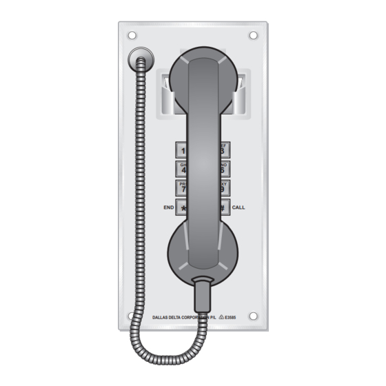
HELP POINT TELEPHONE
S
S
ENTRY
ENTRY
Doorstation
Doorstation
PRESS FOR
PRESS FOR
ATTENTION
ATTENTION
DALLAS DELTA CORPORATION P/L
E3585
N722
Dallas Delta Corporation Pty.Ltd.
VoIP
VOICE OVER IP
G
UARD
Doorstation
MK III
S
ENTRY
Doorstation
102 Albert St. East Brunswick, 3057 Vic.
Tel: 613 93877388 Fax: 613 93873128
Email: sales@dallasdelta.com
www.dallasdelta.com
V2
PRESS BUTTON
FOR ATTENTION
DALLAS DELTA CORPORATION P/L
E3585
DEF
ABC
1
2
3
JKL
GHI
MNO
4
5
6
TUV
WXY
PRS
7
8
9
QZ
0
#
*
ON/OFF
#
PRESS
THEN DIAL NUMBER
#
PRESS
TO END CALL
DALLAS DELTA CORPORATION P/L
E3585
DEF
ABC
1
2
3
GHI
JKL
MNO
5
6
4
PRS
TUV
WXY
7
8
9
QZ
END
0
#
CALL
*
DALLAS DELTA CORPORATION P/L
E3585
Advertisement
Table of Contents

Summary of Contents for DDC Sentry VOIP V2
- Page 1 VoIP HANDS FREE or HANDSET VOICE OVER IP HELP POINT TELEPHONE ENTRY ENTRY Doorstation Doorstation UARD Doorstation MK III PRESS BUTTON FOR ATTENTION PRESS FOR PRESS FOR DALLAS DELTA CORPORATION P/L E3585 ATTENTION ATTENTION CALL ENTRY Doorstation DALLAS DELTA CORPORATION P/L N722 E3585 DALLAS DELTA CORPORATION P/L...
-
Page 2: Table Of Contents
INDEX ........Features ........Operation . -
Page 3: Features
PRODUCT INFORMATION HELP POINT TELEPHONE Model DDC VoIP The Sentry VoIP Doorstation is an ethernet connected telephone and provides voice over internet Protocol (VoIP) communication technology. Giving you the power of our PSTN base units in a IP format. Using a SIP protocol standard (IAX2 , it provides an easy connection to most VoIP based equipment. -
Page 4: Operation
OPERATION The DDC_VoIP telephone operates like a standard hands free telephone with many added features. When the call button is pressed, the unit will establish a call to a preset number. Repressing the call button during a conversation period will terminate the call. A call duration period may be set, if a limit is required. -
Page 5: Keypad Functions
Keypad Functions The keypad on the rear of the unit provides the installer access to: Listen to the current IP address or reset it to a default IP and subnet MASK address. Make test calls and control speaker level during the call. Get current IP address;... -
Page 6: Programming
PROGRAMMING Login page DDC_VoIP door station is programmed by logging into the phones web page. Use a standard web browser (Firefox, Internet Explorer for example), enter the phones IP address into the “URL Location Bar” at the top of the screen. If you don’t know the IP of the phone, then refer to page 5 on ‘Get / Resetting the IP address’. -
Page 7: Network Setup
SETTING MENU On entering the Settings Menu, the current parameters of the telephone will be displayed. Submenu’s are shown on the left of the WEB page, the first section is for ‘Network settings’ and will enable you to change IP address, subnet mask and gateway and option to set DNS server setting. -
Page 8: Voice Menu
Voice In this section, select the order and preferred CODEC’s, plus the amount of frames per packet to sent for each. Also, select the options that effect the different codecs used and DTMF sending method and payloads. When selecting the codecs consider the data rate that will be required by your network. As a guild the list here show the data bit rate required for each codec, if the network is via a low speed ADSL then the PCMu/a may not be a suitable choice. -
Page 9: Sip Proxy Settings
SIP Proxy The parameters on this page will identify the server that will be used for a call setup to and from the DCC_VoIP phone. Your ISP or network administrator will provide the necessary information to be used here. If SIP registration is required with the server then set this switch to Yes. If the phone is configured to dial a direct IP location then this switch can be set to No. -
Page 10: Call Functions
Calling Functions This section controls the way the unit makes and receives calls. Select options, as to what should happen when calls are made to the unit, whether to accept or redirect it, during the different modes of operation. When making calls, numbers may be screened (via the dial plan) or prefix digits can be added. Also, call divert, on busy or no answer. -
Page 11: System Settings
System Settings Set the DDC_VoIP phone audio levels, relay options, Syslog details and time of day functions in this section. Audio levels for each phone should be recheck on site. The on board relay/s may be use for gate access control, back ground lighting / camera. They can be remotely activated or enable when the DDC_VoIP phone is in use. - Page 12 System Settings continue. For some installation, it may be required to record events that occur at the phone. These events may include; " which button is pressed " when a relay is activated remotely " when the handset is on or off hook "...
-
Page 13: Phone Number Menu
PROGRAMMING (Phone Number menu) Button Call Number Assignment The DDC_VoIP phone can be configured with up to 16 buttons, each may be assigned to dial a different telephone number. Click on the Button Call Number Assignment radio button and input the access code, then click ‘Enter’. -
Page 14: Dial Plan Menu
PROGRAMMING (Dial Plan menu) Dial Plan The DDC_VoIP phone can be supplied with a handset and/or a front panel keypad. With this configuration the user may dial any combination of digits, therefore you may wish to screen the phone numbers that can be dialled. This section describes the techniques to accomplish this. Click on the Dial Plan radio button, input the Password and click ‘Enter’. -
Page 15: Changing Ring Tone Menu
PROGRAMMING (Ring Tone) Changing The Ring Tone When a call is made to the DDC_VoIP telephone, the audible sound heard (ringing signal) may be changed to an alternative tone or perhaps a voice message or warning alarm. To change this tone, select the Change Ring Tone option, enter the access Password and click ‘Enter’. -
Page 16: Wiring
WIRING Power Over Ethernet (PoE) The DDC_VoIP telephone may be powered from the 2 way connector marked ‘Power’ on the side of the unit, see page 19. The polarity to this connector must be correct for the unit to function. (Note that NO damage will occur if it is connected incorrectly). The voltage input to this connection may be from 9 to 48 Volts. -
Page 17: Pcb Layout
DDC_VoIP PCB Layout The DDC_VoIP PCB connection may be different from the diagram shown, The layout is of a generic configuration, some items may not be installed and/or not required. RELAY 1+2 KEYPAD NO/NC LINK CONNECTOR LK1 AND LK2 BUTTON INPUTS bank1 RELAY 2 bank2... -
Page 18: Specifications
SPECIFICATIONS power: input voltage Volts - 50 Volts (minimum) (maximum) current -idle mode 60mA @ 13Vdc (0.8 Watts) consumption: -on call 100mA @ 13Vdc (1.3 Watts) normally <300mA @ 13Vdc (3.9Watts) (maximum volume into a 8ohms speaker ) relay contacts: switching maximum 1A @ 60Vdc / 40Vac SELV or TNV (non inductive load) voltage free outputs... -
Page 19: Connection Details
CONNECTION DETAILS ELECTRICAL WIRING Note: On units fitted with external microphone and speaker, the Speaker and microphone are to be mounted no less than Microphone 100 mm apart and sealed well to the panel. OD 17 mm ID 10 mm Grommet dimensions HANDSET Optional External Speaker and Mic. - Page 20 Dallas Delta Corporation Pty.Ltd. 102 Albert St. East Brunswick, 3057 Vic. Tel: 613 93877388 Fax: 613 93873128 Email: sales@dallasdelta.com www.dallasdelta.com Manufacturers of: Emergency Lift Telephones Prisoner Telephones Emergency Telephone Systems Prisoner Phone Monitor Systems Emergency Services Telephones Security Door phones Industrial Telephones Door phones Hygienic Environment Telephones...
Need help?
Do you have a question about the Sentry VOIP V2 and is the answer not in the manual?
Questions and answers